ABB AI625 3BHT300036R1 Retrofit-Ready Analog Input for AC500: Compatible Modernization & Smooth Legacy System Upgrade
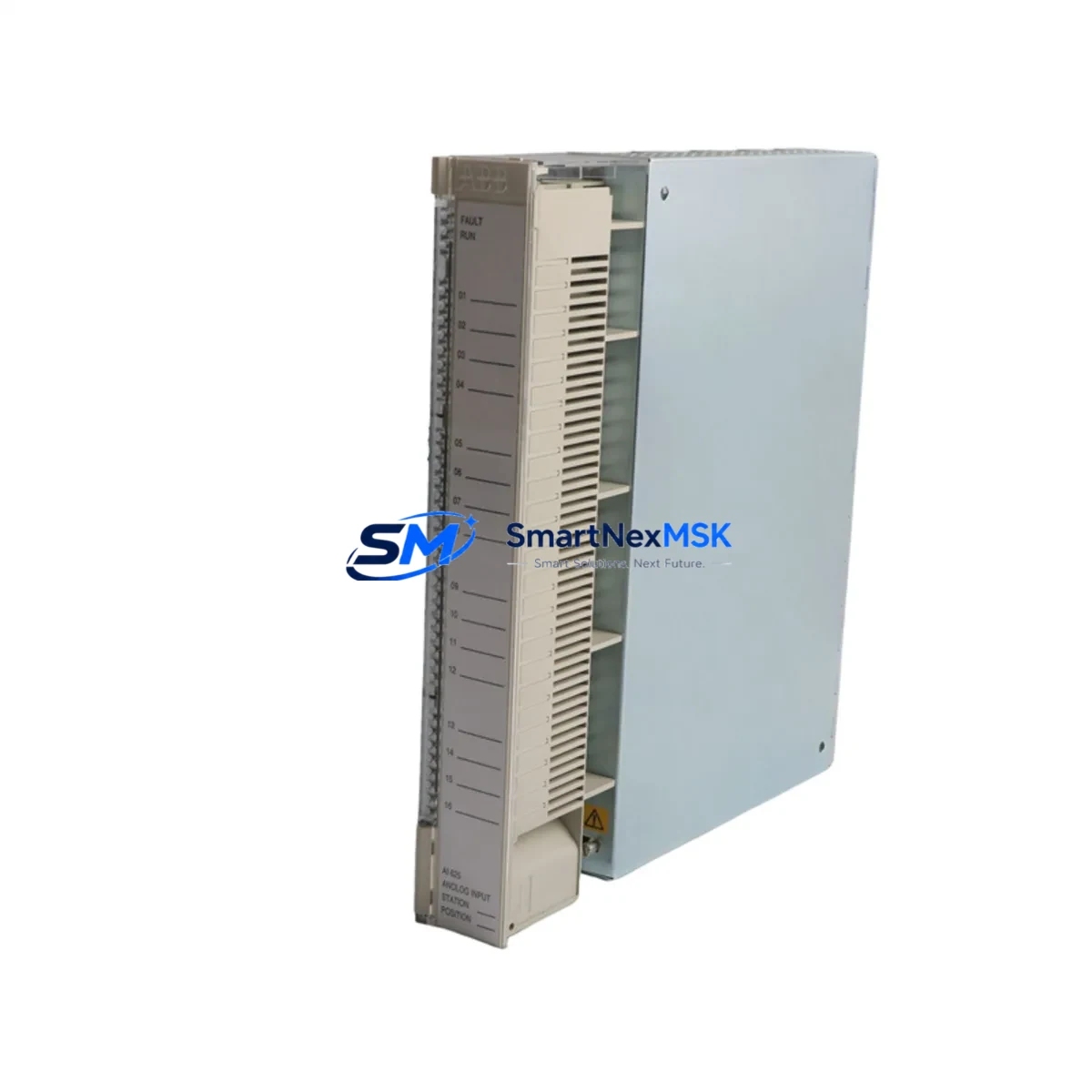
The ABB AI625 3BHT300036R1 is an 8-channel, 16-bit resolution analog input module engineered for the ABB AC500 PLC platform. Designed to accept current (4–20 mA) and voltage (0–10 V) signals, it delivers high-precision process data acquisition for demanding industrial environments including chemical processing, power generation, water treatment, and discrete manufacturing. For facilities operating legacy AC500 installations — or migrating from discontinued third-party analog input hardware — the AI625 3BHT300036R1 represents a verified, drop-in compatible upgrade path that preserves existing wiring infrastructure and control logic.
SMARTNEXMSK maintains ready stock of the AI625 3BHT300036R1 to support urgent retrofit projects, unplanned downtime recovery, and planned system modernization programs. Each unit ships with a 12-month warranty and undergoes pre-shipment functional testing to confirm channel accuracy, terminal integrity, and backplane communication.
Upgrade Compatibility Table
| Parameter | AI625 3BHT300036R1 | Retrofit Notes |
|---|---|---|
| Input Channels | 8 × Analog Input | Direct channel-for-channel replacement in most legacy layouts |
| Resolution | 16-bit | Improved accuracy vs. older 12-bit modules; verify HMI scaling |
| Signal Range | 4–20 mA / 0–10 V | Confirm field transmitter output type before wiring |
| Backplane Interface | AC500 S500 I/O Bus | Compatible with TB511, TB521, TB541 terminal bases |
| Installation | DIN rail / S500 rack | No mechanical modification required for standard AC500 cabinets |
| Communication | AC500 internal I/O bus | Modbus RTU, PROFIBUS DP, CANopen via CPU module — no re-mapping needed |
| Replacement Recommendation | Direct swap for AI620, AI621 series | Verify module address assignment in PS501 Control Builder Plus |
| Commissioning Focus | Channel scaling, filter time, diagnostics enable | Use PS501 to re-download configuration after module swap |
| Warranty | 12 Months | Covers manufacturing defects; pre-shipment functional test included |
Retrofit Planning for Existing Automation Systems
A successful retrofit begins well before the module arrives on site. When replacing an aging analog input card in an AC500-based control system, engineers must audit the full I/O architecture of the affected cabinet. The AI625 3BHT300036R1 mounts directly onto an S500 terminal base — typically a TB511-ETH or TB521 — and communicates with the CPU module (such as the PM573-ETH or PM591) via the internal S500 I/O bus. Before removal of the legacy module, document all terminal wiring assignments and photograph the existing field cable connections to the terminal base.
Power budget verification is a critical pre-retrofit step. The AI625 draws its supply from the backplane; confirm that the existing PS501 power supply module or the rack’s internal bus can support the additional current draw if the AI625 is being added to an existing rack rather than replacing a module of identical type. In multi-rack configurations using an TA526 expansion adapter, verify that the I/O bus extension cable is intact and that the rack address DIP switches are correctly set to avoid address conflicts with other modules such as the AO610 analog output module or DI572 digital input modules sharing the same rack.
For systems migrating from a third-party PLC platform — for example, a Siemens S7-300 with SM331 analog input cards, or a Schneider Modicon M340 with BMX AMI 0410 modules — the AI625 3BHT300036R1 provides a clean migration target when the destination platform is AC500. In these cross-platform migrations, the control program must be rewritten or translated in PS501 Control Builder Plus, and all analog scaling blocks (SCALE_X or equivalent function blocks) must be reconfigured to match the AI625’s 16-bit raw value range. HMI screens built on ABB CP600 operator panels or third-party SCADA systems connected via OPC-UA or Modbus TCP will require tag remapping to reflect the new module’s I/O addresses.
Communication protocol migration is another area requiring careful planning. If the legacy system used PROFIBUS DP for field device communication and the new AC500 configuration uses CM572-DP as the PROFIBUS master, verify that all field instruments — including transmitters, positioners, and remote I/O nodes — are correctly addressed and that the GSD files are loaded into the new project. For systems transitioning to Ethernet-based communication using CM589-PNIO (PROFINET IO), ensure that IP address assignments and device names are configured before the cutover window begins.
Downtime Control During System Migration
Minimizing production downtime during an analog input module replacement requires a structured cutover plan. For the AI625 3BHT300036R1, the recommended approach is a hot-standby preparation strategy: pre-configure the replacement module’s parameters in PS501 Control Builder Plus offline, using a project backup taken from the running system. This allows the engineering team to validate the configuration — including channel enable/disable settings, filter time constants, and diagnostic alarm thresholds — before the physical swap begins.
During the cutover window, follow this sequence to protect program logic and field control continuity:
- Place the CPU (e.g., PM573-ETH) in STOP mode and confirm all outputs are in their safe-state positions.
- De-energize the terminal base power feed and disconnect field signal cables, labeling each wire by channel number.
- Remove the legacy module and install the AI625 3BHT300036R1 onto the terminal base, confirming the module clicks fully into the backplane connector.
- Reconnect field cables in channel order, verifying signal polarity for current-loop inputs.
- Re-energize the terminal base and confirm the module’s status LED indicates normal operation.
- Download the pre-validated configuration from PS501 and return the CPU to RUN mode.
- Monitor all 8 analog channels in the PS501 online diagnostic view for 10–15 minutes to confirm stable, expected process values before releasing control to the operators.
For critical loops — such as pressure or temperature control loops where the analog input feeds a PID function block — consider placing the loop in manual mode at the HMI before the swap and returning to automatic only after channel validation is complete. This approach protects the process from transient signal errors during the module exchange and keeps the overall cutover window under 30 minutes for a single-module replacement.
Retrofit Support FAQ
Q1: Is the AI625 3BHT300036R1 a direct replacement for the AI620 or AI621?
Yes. The AI625 3BHT300036R1 is mechanically and electrically compatible with the same S500 terminal bases used by the AI620 and AI621 series. The primary difference is the 16-bit resolution of the AI625 versus the 12-bit resolution of earlier models. After module swap, re-download the PS501 project to update the module configuration; no hardware wiring changes are required if the terminal base is retained.
Q2: What commissioning steps are required after installation?
After physical installation, connect PS501 Control Builder Plus to the CPU via USB or Ethernet, go online, and perform a hardware configuration download. Verify that the AI625 appears correctly in the I/O tree with its assigned module address. Enable diagnostics for each channel and confirm that live process values match expected field readings. For current-loop inputs, use a calibrated loop calibrator to inject a 4 mA and 20 mA reference signal and verify the raw counts and scaled engineering values in the PS501 watch table.
Q3: Can the AI625 3BHT300036R1 be used in a system that also has AO610 analog output and DI572 digital input modules?
Yes. The AI625 coexists with other S500 I/O modules — including the AO610 analog output, DI572 digital input, and DO572 digital output — on the same S500 rack or expansion rack. Ensure that each module occupies a unique slot address and that the total current draw on the backplane bus does not exceed the PS501 power supply’s rated output. Mixed I/O configurations are standard in AC500 system design and are fully supported by PS501 Control Builder Plus.
Q4: What does the 12-month warranty cover, and is pre-shipment testing performed?
Every AI625 3BHT300036R1 shipped by SMARTNEXMSK undergoes pre-shipment functional testing that verifies backplane communication, all 8 analog input channels, and terminal base connector integrity. The 12-month warranty covers manufacturing defects and functional failures under normal operating conditions. Units showing damage from incorrect wiring, overvoltage, or physical mishandling are not covered. For warranty claims or technical support, contact sales@smartnexmsk.com or call +86 18259474341.
© 2026 SMARTNEXMSK. All rights reserved.
Original Source: https://smartnexmsk.com
Contact: sales@smartnexmsk.com | +86 18259474341


