ABB AI820 3BSE008544R1 Spare for AC500 Automation: Spare Replacement & Industrial Downtime Risk Control
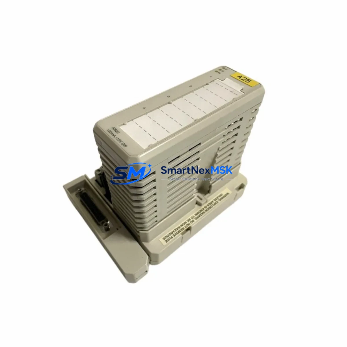
The ABB AI820 (3BSE008544R1) is an original analog input module designed for the ABB AC500 PLC platform — one of the most widely deployed programmable automation controllers in process control, utilities, and discrete manufacturing. When this module fails or degrades, the consequences extend beyond a single I/O channel: the entire control loop dependent on its 4–20 mA or voltage signal inputs is compromised, triggering unplanned downtime, process deviation alarms, and potential safety interlocks. Maintaining a verified spare of the AI820 3BSE008544R1 in your site inventory is a foundational element of any credible maintenance strategy for AC500-based systems.
This listing provides an original, pre-shipment tested ABB AI820 3BSE008544R1 analog input module, sourced and verified for compatibility with the AC500 control platform. Each unit undergoes functional inspection prior to dispatch and is backed by a 12-month warranty, giving maintenance engineers and procurement teams the confidence to stock, deploy, and replace without hesitation.
Spare Maintenance Table
| Parameter | Specification / Detail |
|---|---|
| Part Number | AI820 / 3BSE008544R1 |
| Brand | ABB |
| Series / Platform | AC500 PLC System |
| Module Type | Analog Input Module |
| Input Channels | 8 channels (4–20 mA / 0–10 V configurable) |
| Signal Resolution | 12-bit (typical for AC500 AI series) |
| Backplane Compatibility | AC500 TB5xx / TB5xx-ETH terminal base units |
| Operating Temperature | -25°C to +60°C |
| Mounting | Snap-on to AC500 terminal base; DIN rail compatible |
| Country of Origin | Germany |
| Condition | Original, new or refurbished-to-spec |
| Pre-Shipment Test | Yes — functional verification before dispatch |
| Warranty | 12 Months |
| Application Environment | Industrial automation, process control, utilities, discrete manufacturing |
| Maintenance Recommendation | Inspect signal wiring, terminal base contacts, and firmware version on replacement; verify channel calibration after installation |
Maintenance Planning for Continuous Operation
Replacing the AI820 3BSE008544R1 is rarely an isolated task. In a well-maintained AC500 control cabinet, the analog input module sits at the intersection of field instrumentation and the PLC’s process data — making it a critical node that interacts with multiple upstream and downstream components. A thorough replacement procedure should include inspection of the following:
Begin with the AC500 terminal base (TB511, TB521, or TB541 series) on which the AI820 is mounted. Worn or corroded backplane contacts are a common cause of intermittent signal faults that are misdiagnosed as module failure. Next, verify the AC500 CPU module (PM571, PM581, PM591, or PM595 series) firmware version to confirm compatibility with the replacement AI820 — firmware mismatches can cause channel mapping errors or prevent the module from being recognized on the I/O bus.
Check the 24 VDC power supply module feeding the AC500 rack. Voltage sag or ripple on the supply rail can cause analog input drift and false readings, symptoms that often lead to premature AI820 replacement when the root cause is upstream. If the cabinet uses an AC500 communication module (CM572-DP for PROFIBUS, CM589-PNIO for PROFINET, or CM591-MODTCP for Modbus TCP), verify that the I/O configuration in the engineering tool (Automation Builder) correctly maps the new module’s channel addresses after replacement.
For field-side components, inspect the signal isolators or signal conditioners connected to the AI820 inputs. In older installations, 4–20 mA loop isolators degrade over time and introduce offset errors that appear as AI820 faults. Similarly, check terminal blocks and wiring ferrules in the marshalling cabinet — loose connections on analog signal wiring are a leading cause of noise and signal instability. If the system uses intrinsic safety barriers (Zener barriers or galvanic isolators) for hazardous area instruments, verify their loop resistance and isolation integrity as part of the same maintenance window.
Where the AC500 system interfaces with an HMI panel (CP600 or CP400 series), confirm that analog trend displays and alarm setpoints are functioning correctly after the AI820 swap — this validates end-to-end signal integrity from field sensor to operator interface. Finally, if the installation includes AC500 redundancy modules or a hot-standby CPU configuration, ensure the replacement module is synchronized and recognized by both primary and standby controllers before returning the system to automatic mode.
Site Replacement Workflow
Step 1 — Pre-replacement verification: Confirm the replacement AI820 3BSE008544R1 part number matches the installed module exactly. Cross-reference the label on the existing module with the order documentation. Note the firmware version of the installed module if visible.
Step 2 — Safe isolation: Place the AC500 CPU in STOP mode via Automation Builder or the local keyswitch. Isolate the 24 VDC supply to the affected I/O rack if the system design permits hot-swap; if not, coordinate a controlled process shutdown with the operations team.
Step 3 — Module removal: Disengage the AI820 from the terminal base by releasing the locking tab. Do not disconnect field wiring from the terminal base — the TB design allows module swap without disturbing field connections, which significantly reduces replacement time and eliminates rewiring errors.
Step 4 — Installation and recognition: Seat the replacement AI820 firmly onto the terminal base until the locking tab engages. Power the rack and observe the module status LED. A solid green LED indicates successful recognition. Use Automation Builder to confirm the module appears in the I/O tree with correct channel count.
Step 5 — Channel verification: Apply known reference signals to each input channel and verify readings against expected values. For 4–20 mA loops, a loop calibrator is recommended. Document the as-found and as-left readings in the maintenance record.
Step 6 — Return to service: Switch the CPU to RUN mode, confirm process values are within normal range on the HMI, and clear any maintenance-mode alarms. Update the spare parts log to reflect the consumed unit and initiate a replenishment order to restore buffer stock.
Spare Parts Support FAQ
Q1: Is this AI820 3BSE008544R1 compatible with all AC500 terminal base variants?
The AI820 is designed for the AC500 modular I/O system and is compatible with the TB511, TB521, and TB541 terminal base families. Compatibility with specific terminal bases depends on the channel configuration and wiring scheme of your installation. We recommend confirming the terminal base part number before ordering if your system uses a non-standard configuration.
Q2: What pre-shipment testing is performed on each unit?
Each AI820 3BSE008544R1 unit undergoes functional verification prior to dispatch, including power-on test, channel response check, and visual inspection for physical integrity. Units that do not pass functional verification are not shipped. A test report is available upon request for critical applications.
Q3: How should I manage AI820 spare stock for a multi-cabinet AC500 installation?
For installations with three or more AC500 racks using AI820 modules, we recommend maintaining a minimum of one spare per site, with a second unit held at regional warehouse level for rapid deployment. Given the 12-month warranty on supplied units, a rolling stock rotation policy — replacing the oldest spare first — ensures warranty coverage is always active on the unit most likely to be deployed next.
Q4: Can this module replace older or discontinued ABB AC500 analog input variants?
The AI820 3BSE008544R1 is the current production part number for this module family. It is designed as a direct replacement for earlier revisions of the AI820 within the AC500 platform. For legacy AC500 systems using earlier I/O generations, compatibility should be verified against the system’s hardware configuration file in Automation Builder before installation. Our technical team can assist with compatibility confirmation prior to order.
© 2026 SMARTNEXMSK. All rights reserved.
Original Source: https://smartnexmsk.com
Contact: sales@smartnexmsk.com | +86 18259474341


