ABB ATMB-01C Retrofit-Ready Terminal Bus for AC500 Control Systems
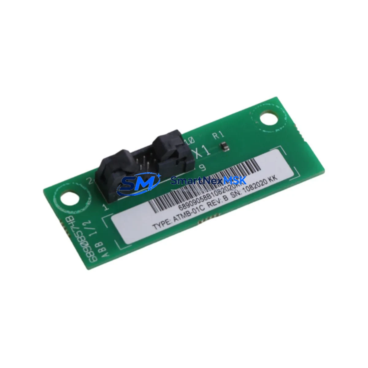
The ABB ATMB-01C is a terminal bus module engineered for seamless integration into ABB AC500 series programmable logic controller platforms. Designed to support legacy system modernization, this module serves as a direct retrofit replacement for aging or discontinued terminal bus components within AC500 control cabinets. Whether you are upgrading a production line, recovering from a component failure, or migrating from an older AC500 variant, the ATMB-01C provides the electrical and mechanical compatibility required to minimize engineering rework and reduce total downtime.
Industrial facilities operating ABB AC500 PM5xx or PM5xx-ETH CPU modules frequently encounter the need to replace or expand their terminal bus infrastructure as part of broader control system upgrades. The ATMB-01C slots directly into the AC500 backplane, maintaining compatibility with the standard I/O bus architecture used across the AC500 family. Engineers replacing legacy terminal bus modules should verify backplane slot assignments, confirm module addressing in the PS501 Control Builder Plus programming environment, and validate that existing I/O channel mappings remain intact after substitution.
When planning a retrofit involving the ATMB-01C, the following verification steps are critical: confirm the power supply module — such as the AC500 CP600 or TA526 power terminal adapter — can sustain the additional bus load; inspect terminal wiring for compatibility with the module’s screw-terminal pitch; verify that the TB521-ETH or TB523 communication interface modules on the same rack are not affected by bus address reassignment; and confirm that any connected S500 I/O modules, including digital input modules like DI524 or analog output modules like AO523, retain their configured channel addresses post-swap.
For systems that include HMI integration via ABB CP600 operator panels or third-party SCADA platforms communicating over Modbus TCP or PROFIBUS DP, engineers must validate that HMI screen variable bindings remain aligned with the updated I/O structure. Communication links between the AC500 CPU and field devices — including remote I/O stations connected via the AC500’s built-in PROFIBUS or Ethernet/IP interfaces — should be tested under live conditions before returning the system to full production.
In multi-rack configurations, the ATMB-01C supports expansion through the AC500’s standard rack interconnect system. When used alongside the TA526 terminal adapter or in conjunction with the TB511-ETH bus terminal, the module maintains signal integrity across extended backplane distances. Replacement planning should account for the physical rack dimensions, DIN rail mounting clearances, and any adjacent modules that may require temporary removal during installation.
All ATMB-01C units supplied by SMARTNEXMSK are sourced from verified industrial supply channels, pre-inspected prior to dispatch, and covered by a 12-month warranty against manufacturing defects. Units are available from stock for immediate shipment, supporting urgent maintenance scenarios and planned shutdown windows alike.
Upgrade Compatibility Table
| Parameter | Detail |
|---|---|
| SKU | ATMB-01C |
| Brand | ABB |
| Compatible Series | AC500 (PM5xx, PM5xx-ETH) |
| Module Type | Terminal Bus Module |
| Backplane Interface | AC500 Standard I/O Bus |
| Mounting | DIN Rail / AC500 Rack |
| Communication Compatibility | PROFIBUS DP, Modbus TCP, Ethernet/IP (via CPU) |
| Wiring Compatibility | Standard AC500 screw-terminal pitch |
| Replacement Recommendation | Direct drop-in for legacy ATMB terminal bus modules |
| Programming Environment | PS501 Control Builder Plus |
| Commissioning Notes | Verify slot address, I/O channel mapping, and HMI variable bindings post-installation |
| Warranty | 12 Months — covers manufacturing defects, includes pre-shipment inspection |
| Origin | Germany |
| Stock Status | Available — fast global shipping |
Retrofit Planning for Existing Automation Systems
A successful ATMB-01C retrofit begins with a thorough audit of the existing control cabinet. Technicians should document the current rack layout, noting the positions of all installed modules including the AC500 CPU (e.g., PM564-T or PM591-ETH), power supply units, and any S500 I/O modules such as the DI524 digital input module or AO523 analog output module. The TA526 terminal adapter and any TB521-ETH or TB523 bus terminal modules in the rack must be accounted for, as their addressing may be affected by changes to the terminal bus configuration.
Before removing the legacy terminal bus module, engineers should export the current project from PS501 Control Builder Plus and create a full backup of the CPU program, including all function block diagrams, structured text routines, and I/O variable declarations. If the system includes a CP600 HMI panel, a backup of the HMI project should also be taken to preserve screen layouts and variable tag assignments. Communication parameters for any PROFIBUS DP slave devices or Modbus TCP-connected instruments should be recorded and verified against the new module’s configuration after installation.
Power budget verification is essential: confirm that the AC500 power supply module can support the combined load of all installed I/O and communication modules after the ATMB-01C is installed. In systems where the rack is near its power capacity, consider redistributing modules or adding a supplementary power supply before proceeding with the retrofit.
Downtime Control During System Migration
Minimizing production downtime during an ATMB-01C replacement requires careful pre-staging and a structured cutover plan. Where possible, prepare the replacement module in advance by configuring its address settings to match the outgoing unit before the scheduled maintenance window. Use the PS501 Control Builder Plus offline simulation mode to validate the updated I/O configuration against the existing program logic without requiring a live system connection.
During the physical swap, follow a structured sequence: isolate the rack power supply, remove the legacy terminal bus module, install the ATMB-01C, restore power, and perform a controlled CPU restart. After restart, verify that all S500 I/O modules — including any DI524, DO524, or AO523 units in the rack — are recognized by the CPU and that their channel statuses are reported correctly in the Control Builder Plus diagnostics view. Confirm that PROFIBUS DP communication to field devices and any Ethernet/IP connections to remote I/O stations are re-established without fault.
For systems where continuous operation is critical, consider implementing a hot-standby or redundant CPU configuration using the AC500’s redundancy options before undertaking terminal bus maintenance. This allows the standby CPU to maintain field control while the primary rack undergoes the retrofit, effectively reducing process interruption to near zero.
Retrofit Support FAQ
Q: Is the ATMB-01C a direct replacement for the original terminal bus module in my AC500 rack?
A: Yes. The ATMB-01C is designed as a drop-in replacement for legacy terminal bus modules within the AC500 platform. It maintains the same backplane interface, screw-terminal pitch, and DIN rail mounting dimensions, allowing substitution without mechanical modification to the existing rack or wiring.
Q: Do I need to reprogram my AC500 CPU after installing the ATMB-01C?
A: In most cases, no reprogramming is required if the module address and slot position are configured to match the outgoing unit. However, engineers should perform a full I/O diagnostic scan in PS501 Control Builder Plus after installation to confirm that all channel mappings and variable bindings are intact before returning the system to automatic operation.
Q: How do I verify wiring compatibility before installation?
A: Compare the terminal pitch and wiring diagram of the ATMB-01C against the existing module using the ABB AC500 hardware documentation. In most AC500 retrofit scenarios, the standard screw-terminal layout is preserved, allowing existing field wiring to be reconnected without modification. Always verify conductor cross-sections and torque specifications against the module datasheet.
Q: What does the 12-month warranty cover, and how is pre-shipment testing conducted?
A: All ATMB-01C units supplied by SMARTNEXMSK are inspected prior to dispatch to verify physical integrity and basic electrical function. The 12-month warranty covers manufacturing defects identified under normal operating conditions. Units showing damage resulting from incorrect installation, overvoltage, or environmental factors outside the module’s rated specifications are not covered. Contact sales@smartnexmsk.com for warranty claims or technical support.
© 2026 SMARTNEXMSK. All rights reserved.
Original Source: https://smartnexmsk.com
Contact: sales@smartnexmsk.com | +86 18259474341


