ABB AV31 Maintenance-Ready Spare for AV Series Automation
The ABB AV31 Indication Unit Board is a critical original spare component within the ABB AV Series annunciator and relay protection ecosystem. Designed for continuous-duty industrial environments, the AV31 serves as the front-end indication interface in relay protection panels, switchgear control cabinets, and substation automation systems. For maintenance engineers managing aging control infrastructure, securing a verified AV31 spare is a direct risk-mitigation measure against unplanned downtime and extended outage windows.
Whether you are executing a planned shutdown inspection, responding to an annunciator fault alarm, or building a strategic spare parts inventory for a critical facility, the AV31 must be treated as a high-priority line item. Its failure mode — loss of indication and alarm acknowledgment capability — directly impairs operator situational awareness and can delay fault isolation in high-voltage protection circuits. Replacement with an original ABB AV31 ensures full compatibility with existing AV Series panel wiring, terminal assignments, and relay logic without requiring firmware reconfiguration or panel re-engineering.
Spare Maintenance Table
| Parameter | Specification / Detail |
|---|---|
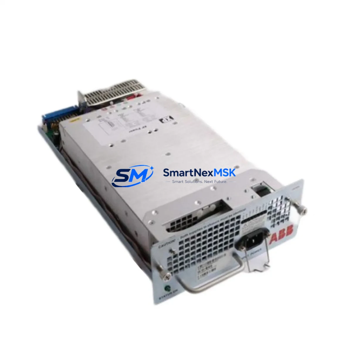
| SKU / Part Number | AV31 |
| Brand | ABB |
| Series | AV Series (Annunciator / Indication Unit) |
| Product Type | Relay Protection Accessories — Indication Unit Board |
| Origin | Germany (DE) |
| Compatibility | ABB AV Series relay protection panels; annunciator systems with standard AV-type indication modules |
| Mounting / Installation | Panel-mount, plug-in module; compatible with standard AV Series backplane and terminal rail |
| Operating Environment | Industrial control cabinets, substation relay rooms, switchgear panels; suitable for continuous-duty operation |
| Signal Interface | Hardwired indication inputs; compatible with relay contact outputs and annunciator logic circuits |
| Replacement Scope | Direct replacement for worn, damaged, or end-of-life AV31 units; no panel re-wiring required when replacing like-for-like |
| Pre-shipment Testing | Function-verified before dispatch; visual inspection and continuity check completed |
| Warranty | 12 Months from date of shipment |
| Lead Time | In-stock units dispatched within 1–3 business days |
Maintenance Planning for Continuous Operation
When a maintenance or procurement engineer schedules replacement of the ABB AV31, the surrounding electrical circuit and control cabinet should be inspected simultaneously to prevent repeat failures and maximize the value of each planned outage window. The AV31 operates within a broader relay protection and annunciator architecture, and its performance is directly influenced by the condition of adjacent components.
Begin with the ABB AV Series power supply module feeding the indication panel — verify output voltage stability and check for capacitor aging or ripple that could cause intermittent AV31 resets. Inspect the relay output contacts (such as those from ABB REF615 or REX640 protection relays) that drive the AV31 indication inputs; worn or oxidized contacts produce false alarms or missed indications. Check the terminal blocks and wiring harness connecting the AV31 to the panel backplane — loose terminations are a leading cause of indication failures in high-vibration environments.
If the panel includes an ABB COM600 or COM610 communication gateway, verify that the SCADA data path for alarm acknowledgment remains intact after AV31 replacement. For panels with signal isolators between field devices and the indication circuit, inspect the isolator output range and zero-drift — a degraded isolator can produce spurious AV31 alarm states. Review the condition of miniature circuit breakers (MCBs) and fuse holders on the 24 VDC or 48 VDC auxiliary supply rail; a marginal fuse can cause the AV31 to drop out under load transients.
For systems with an ABB CP600 or CP400 HMI panel integrated into the same control cabinet, confirm that the HMI alarm list and AV31 indication mapping remain synchronized after the module swap. Where I/O expansion modules (such as ABB AI810 or DI810 in a DCS context) feed status signals into the annunciator circuit, verify channel integrity and signal scaling. Finally, inspect the cabinet door sealing, ventilation filters, and thermal management — overtemperature is a primary accelerant of indication board degradation in outdoor or poorly ventilated switchgear rooms.
Building a co-located spare kit that includes the AV31 alongside a spare AV Series backplane connector, a set of labeled terminal ferrules, and a spare auxiliary power fuse will reduce mean-time-to-repair (MTTR) to under 30 minutes for a trained technician.
Site Replacement Workflow
Step 1 — Isolation and Permit: Isolate the relay protection panel from live circuits per site LOTO procedure. Confirm auxiliary supply de-energization with a calibrated voltage tester before opening the cabinet.
Step 2 — Documentation: Photograph the existing AV31 wiring, terminal labels, and module position before removal. Record the current alarm acknowledgment state from the HMI or SCADA system.
Step 3 — Module Removal: Release the AV31 from its backplane connector using the module extraction tool or a flat-blade screwdriver at the designated release tab. Do not apply lateral force to the PCB edge.
Step 4 — Inspection: Inspect the backplane connector pins for corrosion, deformation, or contamination. Clean with isopropyl alcohol if required. Check the terminal rail for loose screws.
Step 5 — Installation: Seat the replacement AV31 firmly into the backplane connector until the retention latch engages. Verify module alignment with adjacent AV Series units.
Step 6 — Energization and Functional Test: Restore auxiliary supply. Confirm all indication channels display correct status. Perform an alarm acknowledgment test from the local panel and from the SCADA/HMI system. Document the replacement in the site maintenance log.
This workflow applies equally to planned maintenance replacements and emergency fault-response scenarios. Using an original ABB AV31 spare eliminates compatibility risk and ensures the replaced unit meets the original panel design specification without modification.
Spare Parts Support FAQ
Q1: Is the AV31 compatible with all ABB AV Series annunciator panels?
The AV31 is designed for the ABB AV Series indication unit architecture. Compatibility should be confirmed against your specific panel model and backplane revision. Our technical team can assist with cross-referencing your panel drawing or nameplate data prior to order confirmation.
Q2: What pre-shipment checks are performed on the AV31?
Each AV31 unit undergoes visual inspection for physical damage, connector pin integrity check, and basic continuity verification before dispatch. Units are packed in anti-static protective packaging with a shipment inspection record included.
Q3: What does the 12-month warranty cover?
The 12-month warranty covers manufacturing defects and functional failures under normal operating conditions from the date of shipment. It does not cover damage resulting from incorrect installation, overvoltage events, or environmental exposure beyond the rated operating range. Warranty claims are processed with return authorization and fault documentation.
Q4: Can you support long-term or repeat supply of the AV31 for multi-site maintenance programs?
Yes. We support blanket order arrangements and scheduled delivery programs for maintenance teams managing multiple sites or aging relay protection fleets. Contact our sales team to discuss volume pricing, reserved stock agreements, and lead-time commitments for your annual maintenance plan.
© 2026 SMARTNEXMSK. All rights reserved.
Original Source: https://smartnexmsk.com
Contact: sales@smartnexmsk.com | +86 18259474341


