ABB AX521 Retrofit-Ready Analog I/O for AC500 Control Systems
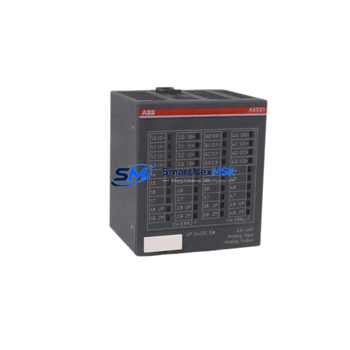
The ABB AX521 is an 8-channel analog input / 4-channel analog output module engineered for the AC500 PLC platform. Designed to support both new installations and legacy system modernization, the AX521 delivers reliable signal conditioning across 4–20 mA current loops and ±10 V voltage ranges — making it a direct retrofit candidate for aging AC500 control cabinets where the original module has been discontinued, damaged, or is no longer available through standard distribution channels.
For engineers managing brownfield automation upgrades, the AX521 represents a proven, drop-in compatible solution that eliminates the need for full PLC replacement. Whether you are restoring a production line after an unplanned failure or executing a planned control system modernization, the AX521 integrates directly into existing AC500 backplane slots without requiring changes to the CPU program structure, I/O addressing, or HMI tag mapping — provided the firmware version of the host CPU module is compatible.
Upgrade Compatibility Table
| Parameter | Details |
|---|---|
| Compatible Platform | ABB AC500 PLC Series (PM571, PM581, PM591, PM595) |
| Analog Inputs | 8 × AI — 4–20 mA / 0–10 V / ±10 V selectable |
| Analog Outputs | 4 × AO — 4–20 mA / 0–10 V |
| Backplane Interface | AC500 S500 I/O bus — direct slot insertion, no adapter required |
| Installation Requirement | DIN rail mount; compatible with TB521, TB541 terminal bases |
| Communication Compatibility | Modbus RTU, PROFIBUS DP (via CM572-DP coupler), CANopen |
| Replacement Recommendation | Direct replacement for discontinued AX521 units; verify CPU firmware ≥ V2.x |
| Commissioning Notes | Re-map I/O addresses in Automation Builder if slot position changes; verify signal scaling |
| Warranty | 12-Month Warranty — covered against manufacturing defects and functional failure |
Retrofit Planning for Existing Automation Systems
Successful integration of the AX521 into a legacy AC500 control system requires a structured pre-installation review. Begin by auditing the existing control cabinet layout: confirm the available backplane slots on the S500 I/O rack and verify that the TB521 or TB541 terminal base currently installed is compatible with the AX521 footprint. In many retrofit scenarios, the terminal base can be retained, which significantly reduces field wiring time and minimizes the risk of miswiring during the changeover.
Power budget verification is a critical step that is frequently overlooked. The AC500 CPU module — whether a PM571, PM581, or PM591 — supplies backplane power to all connected I/O modules. Adding or replacing an AX521 requires confirming that the total current draw across all installed modules does not exceed the CPU’s rated backplane supply capacity. If the existing rack is already near its power limit, a PS501 power supply module or a secondary rack expansion may be required before the AX521 can be safely commissioned.
Terminal wiring should be documented and photographed before any module is removed. The AX521 uses a standard screw-terminal layout on the TB521 base, with clearly labeled AI+, AI−, AO+, and AO− positions. When replacing a failed module, cross-reference the original wiring diagram against the AX521 datasheet to confirm signal polarity and shielding requirements — particularly for 4–20 mA transmitters connected to pressure, temperature, or flow sensors in the field.
For systems using PROFIBUS DP as the primary fieldbus, the AX521 communicates through the CM572-DP communication module mounted on the CPU rack. Confirm that the GSD file version loaded in the PROFIBUS master configuration matches the AX521 firmware. In installations where the control network has been migrated from PROFIBUS to Modbus TCP or EtherNet/IP, a CM589-PNIO or CM579-ETHCAT coupler may be required alongside the AX521 to maintain full I/O visibility at the SCADA or DCS level.
HMI screen validation is another essential step in the retrofit workflow. If the plant uses a CP600 or CP620 operator panel connected to the AC500 CPU via the internal serial port or Ethernet, verify that all analog tag addresses referenced in the HMI project still resolve correctly after the AX521 is installed. A mismatch between the I/O module slot assignment in Automation Builder and the HMI tag database will result in stale or incorrect process values being displayed — a condition that can trigger nuisance alarms or, in worst cases, incorrect operator interventions.
Downtime Control During System Migration
Minimizing unplanned downtime during an AX521 retrofit requires a disciplined hot-swap and pre-staging approach. Where the AC500 CPU supports online module replacement — available on PM591 and PM595 platforms with appropriate firmware — the AX521 can be inserted into a powered rack without a full system shutdown, provided the I/O channel is placed in a safe state (output forced to 0 mA or 0 V) before the physical swap is performed.
For older PM571 or PM581 installations that do not support hot-swap, plan the replacement during a scheduled maintenance window. Before powering down, export a full backup of the Automation Builder project, including the hardware configuration, program logic, and communication settings. Store this backup on an external drive and verify it can be restored to a spare CPU module — this ensures that if the replacement procedure encounters an unexpected issue, the original control logic can be recovered without delay.
During the physical replacement, retain the original AX521 terminal base in position and swap only the module body. This approach preserves all field wiring connections and eliminates the need to re-terminate individual conductors — a process that, on a fully wired 8-channel analog input module, can add 30–60 minutes to the outage window. Once the new AX521 is seated and the system is powered on, use the Automation Builder diagnostic view to confirm that all 8 analog input channels and 4 analog output channels are reporting correctly before releasing the process back to automatic control.
For multi-rack installations where the AX521 is one of several modules being upgraded — alongside DC532 digital I/O modules, AO523 analog output modules, or AI523 analog input modules — sequence the replacements by rack section to maintain partial system availability throughout the migration. Document each completed module swap in the site maintenance log, including the serial number of the replaced unit and the firmware version of the new module, to support future audits and warranty claims.
Retrofit Support FAQ
Q1: Is the AX521 a direct drop-in replacement for a failed or discontinued ABB AC500 analog I/O module?
Yes. The AX521 is designed for direct slot-compatible installation in AC500 S500 I/O racks using the TB521 or TB541 terminal base. No hardware adapters or wiring modifications are required in most standard retrofit scenarios. Confirm the CPU firmware version supports the AX521 hardware revision before installation.
Q2: What commissioning steps are required after installing the AX521 in an existing AC500 system?
After physical installation, open the Automation Builder project and perform a hardware scan to confirm the AX521 is recognized in the correct rack slot. Verify I/O channel addressing, check signal scaling parameters for each analog input, and force-test each analog output channel to confirm correct mA or voltage output at the field device. For PROFIBUS-connected systems, confirm the GSD configuration is consistent with the installed module firmware.
Q3: Can the AX521 be used in a system that has been migrated from PROFIBUS DP to Modbus TCP?
Yes. The AX521 itself communicates via the AC500 backplane bus and is protocol-agnostic at the module level. The communication protocol used to connect the AC500 CPU to upstream SCADA or DCS systems is determined by the communication coupler — such as the CM589-PNIO for PROFINET or the CM579-ETHCAT for EtherCAT — not by the I/O module. The AX521 will function correctly regardless of which fieldbus protocol is active on the CPU rack.
Q4: What does the 12-month warranty cover, and what is the process for a warranty claim?
The 12-month warranty covers manufacturing defects and functional failures under normal operating conditions. Each AX521 unit is tested prior to shipment, and a test report is available upon request. To initiate a warranty claim, contact sales@smartnexmsk.com with the order reference, module serial number, and a description of the observed fault. Replacement units are dispatched within 3–5 business days upon claim verification.
© 2026 SMARTNEXMSK. All rights reserved.
Original Source: https://smartnexmsk.com
Contact: sales@smartnexmsk.com | +86 18259474341


