ABB BDPS-11C Retrofit-Ready Drive Module for BDPS Series: Compatible Modernization for Existing Control Systems
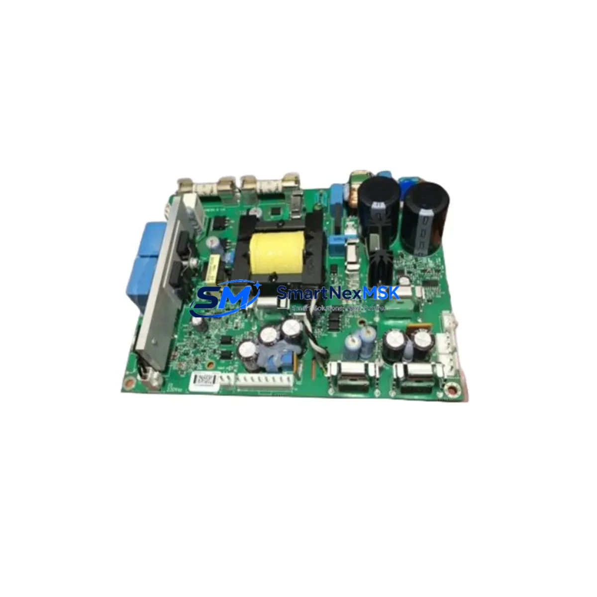
The ABB BDPS-11C is a drive control module engineered for seamless integration into BDPS Series variable frequency drive systems. Whether you are managing a planned upgrade, responding to an end-of-life notification, or sourcing a critical spare for an aging production line, the BDPS-11C delivers the electrical compatibility, mechanical fit, and communication protocol alignment required for a reliable retrofit without redesigning your existing control architecture.
Industrial facilities running legacy ABB ACS or SDCS drive platforms frequently encounter the challenge of sourcing replacement modules when original components are discontinued. The BDPS-11C addresses this directly by maintaining backward compatibility with the BDPS drive series backplane, preserving existing terminal wiring layouts and I/O channel assignments. Engineers can install this module without rewiring field cables or modifying PLC address tables, significantly reducing the risk of commissioning errors during a live system changeover.
Upgrade Compatibility Table
| Parameter | Details |
|---|---|
| Compatible Series | ABB BDPS Drive Series |
| Module SKU | BDPS-11C |
| Backplane Interface | BDPS Series standard backplane slot |
| Terminal Wiring | Direct match to original BDPS-11C pinout |
| Communication Protocol | Compatible with DDCS / PROFIBUS-DP as configured in host drive |
| Installation Requirement | No mechanical modification required; slot-in replacement |
| Replacement Recommendation | Suitable for 1:1 swap of discontinued BDPS-11C units |
| Commissioning Note | Verify drive firmware version and parameter set before power-on |
| Warranty | 12 Months from date of shipment |
Retrofit Planning for Existing Automation Systems
A successful BDPS-11C retrofit begins well before the module arrives on site. Maintenance engineers should audit the existing control cabinet to confirm available power supply capacity — the BDPS Series power supply module (such as the APBU-44C or equivalent distribution board) must be verified to support the current draw of the replacement module under full load conditions. Terminal block assignments on the NTAC or NDIO I/O extension modules connected to the same rack should be documented before any hardware is removed.
In systems where the BDPS-11C interfaces with a higher-level controller — for example, an ABB AC500 PLC or a third-party Siemens S7-300 via a PROFIBUS-DP link — the module address configuration stored in the drive’s parameter memory must be confirmed against the PLC’s hardware configuration file. Mismatched node addresses are a common source of communication faults during post-retrofit startup. If the site uses an ABB Panel Builder or CP600 HMI, verify that the HMI tag database references the correct drive object identifiers before going live.
For facilities migrating from older SDCS DC drive platforms to the BDPS AC architecture, additional steps are required: the SNAT 601 or SNAT 607 control boards in the legacy system must be fully decommissioned and their I/O signals remapped to the new BDPS I/O structure. Programming cables such as the RUSB-02 or OPFA-01 fiber adapter may be needed to access drive parameters during the migration phase. Ensure that the DRIVEWINDOW or Drive Composer commissioning software version is compatible with the target firmware loaded on the BDPS drive unit.
Rack and chassis integrity should also be inspected during the retrofit window. Backplane connectors on aged BDPS racks can develop oxidation that causes intermittent communication errors after module replacement. Cleaning connector surfaces and verifying rack grounding continuity are low-cost steps that prevent post-installation faults. If the control cabinet houses multiple drive modules sharing a common DDCS fiber ring, the ring topology must remain intact throughout the swap to avoid disrupting other drives on the same network segment.
Downtime Control During System Migration
Minimizing production downtime during a BDPS-11C replacement requires a structured changeover plan. Begin by exporting the full parameter set from the existing drive using Drive Composer or DRIVEWINDOW before powering down. Store this backup on a secure engineering workstation — it serves as the restore baseline if the new module requires parameter reloading after installation.
Where process continuity is critical, coordinate the module swap during a scheduled maintenance window rather than responding reactively to a failure. Pre-stage the BDPS-11C alongside any ancillary components — such as replacement DDCS fiber cables, spare APBU distribution fuses, or updated PROFIBUS termination resistors — so that the physical installation can be completed within a single shift. After installation, restore parameters from the backup file, verify I/O channel mapping against the original wiring diagram, and perform a no-load test run before reconnecting the driven equipment. This sequence protects the original program logic and ensures field control continuity from the first powered cycle.
Retrofit Support FAQ
Q: Is the BDPS-11C a direct 1:1 replacement for the original module?
A: Yes. The BDPS-11C is designed as a drop-in replacement for the original BDPS-11C module. Terminal pinout, backplane connector, and mechanical dimensions are matched to the original specification. No cabinet modifications are required.
Q: What commissioning steps are required after installation?
A: After physical installation, restore the drive parameter set from a pre-swap backup using Drive Composer or DRIVEWINDOW. Verify communication node address, I/O channel assignments, and HMI tag references before enabling the drive. A no-load test run is recommended prior to reconnecting the driven load.
Q: How is wiring compatibility confirmed before ordering?
A: Provide your existing drive model number, firmware version, and terminal wiring diagram to our technical team. We will confirm compatibility against the BDPS-11C specification sheet and advise on any adapter requirements before shipment.
Q: What does the 12-month warranty cover?
A: All units are tested prior to shipment and covered by a 12-month warranty against manufacturing defects under normal operating conditions. Warranty support includes technical assistance for installation and commissioning issues arising from the module itself.
© 2026 SMARTNEXMSK. All rights reserved.
Original Source: https://smartnexmsk.com
Contact: sales@smartnexmsk.com | +86 18259474341


