ABB BX5001 GNT0156100R1 Maintenance-Ready Spare AC500 Automation
The ABB BX5001 (part number GNT0156100R1) is an original expansion module designed for the ABB AC500 programmable logic controller series — one of the most widely deployed PLC platforms in process automation, machine control, and critical infrastructure applications worldwide. For maintenance engineers managing aging control systems, the BX5001 represents a high-priority spare: its failure directly impacts I/O availability, loop integrity, and system uptime. Stocking a verified original replacement is the most effective strategy to minimize unplanned downtime and protect production continuity.
This unit is sourced as an original ABB component, fully tested prior to shipment, and backed by a 12-month warranty. It is suitable for planned maintenance cycles, emergency replacement, and long-term spare parts inventory programs for facilities operating AC500-based control architectures.
Spare Maintenance Table
| Parameter | Specification / Detail |
|---|---|
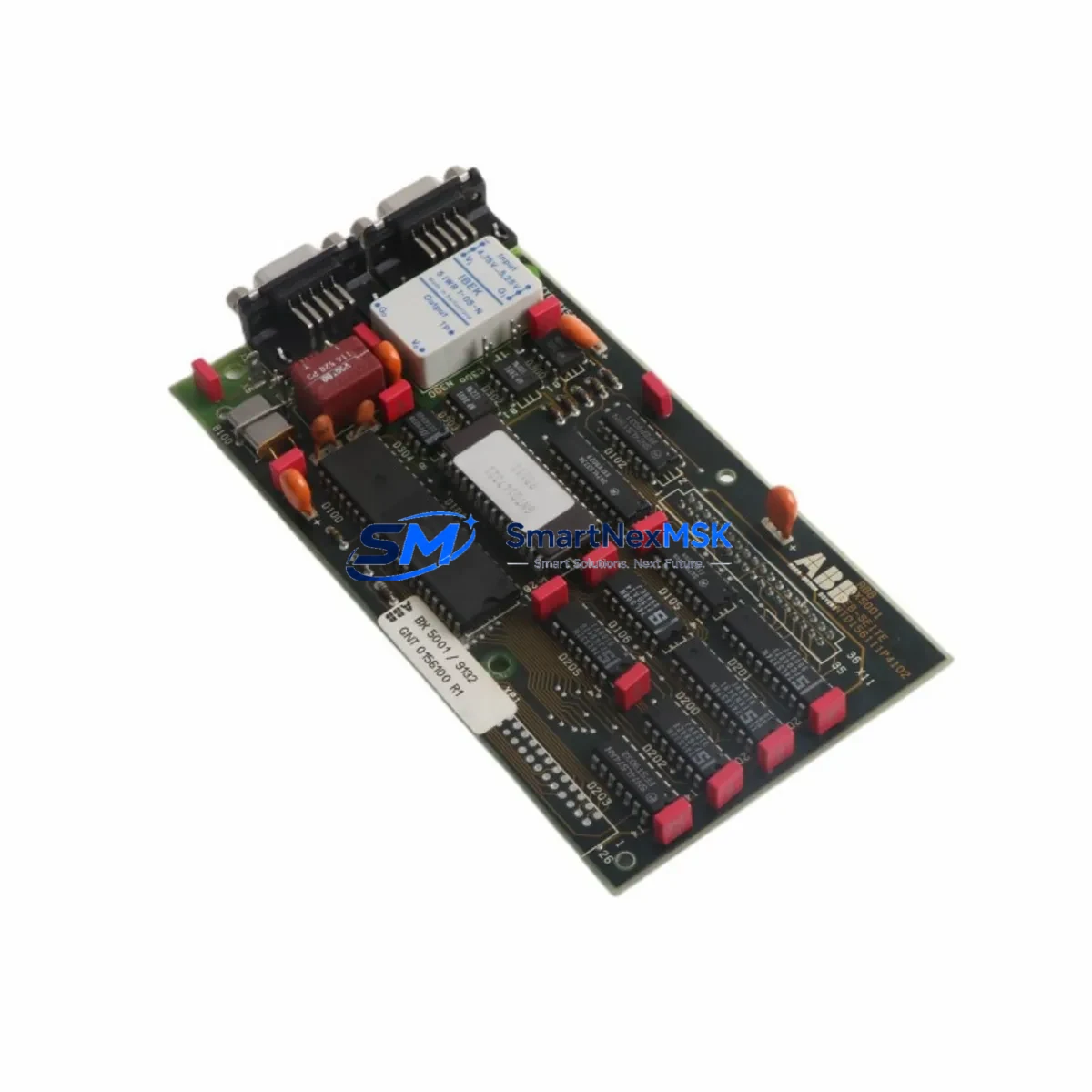
| Part Number | GNT0156100R1 |
| Model | BX5001 |
| Brand | ABB |
| Compatible Series | ABB AC500 PLC Series (PM5xx CPUs) |
| Module Function | Communication / Expansion Bus Interface Module |
| Mounting | Direct backplane mounting on AC500 terminal base |
| Operating Voltage | 24 V DC (supplied via backplane) |
| Operating Temperature | -25 °C to +70 °C |
| Protection Class | IP20 |
| Certifications | CE, UL (per AC500 platform standards) |
| Country of Origin | Germany |
| Condition | Original, New |
| Pre-shipment Testing | Yes — functional verification before dispatch |
| Warranty | 12 Months |
| Typical Application | Process automation, machine control, utility infrastructure |
| Maintenance Recommendation | Inspect connector pins and backplane contacts during scheduled shutdowns; replace if communication errors or CRC faults are logged |
Maintenance Planning for Continuous Operation
When the BX5001 GNT0156100R1 is identified as a replacement candidate during a control cabinet inspection or fault diagnosis, experienced maintenance engineers know that a single-module swap rarely tells the whole story. A thorough site assessment should accompany any BX5001 replacement to prevent repeat failures and ensure the restored system operates reliably through the next maintenance interval.
Begin by verifying the 24 V DC power supply module feeding the AC500 backplane — voltage sag or ripple is a common root cause of intermittent communication faults that are incorrectly attributed to the expansion module itself. Inspect the TB5xx terminal base on which the BX5001 is seated: damaged locking tabs, corroded contacts, or cracked housings require base replacement before installing the new module. Check the PM5xx CPU module firmware version to confirm compatibility with the replacement BX5001 hardware revision, as mismatched firmware can cause bus initialization failures.
Review the DI5xx digital input modules and DO5xx digital output modules on the same backplane segment — if the BX5001 failure was caused by an upstream surge or wiring fault, adjacent I/O modules may have sustained latent damage that will only manifest under load. Inspect all field wiring terminal blocks for loose connections, insulation breakdown, or moisture ingress, particularly in environments with vibration or thermal cycling.
For systems using fieldbus communication, verify the CM5xx communication module (PROFIBUS, Modbus, or EtherNet/IP variant as applicable) is logging clean bus traffic after the BX5001 is restored. If the control cabinet includes signal isolators or loop-powered transmitters, confirm that 4–20 mA signal integrity is maintained across all critical process loops. Where CP6xx HMI panels are connected to the AC500 CPU, validate that the operator interface re-establishes communication correctly and that no alarm states are masked post-restart.
Finally, check the 24 V DC fuse or circuit breaker protecting the backplane power rail — a nuisance trip that preceded the BX5001 fault may indicate an underlying overcurrent condition that must be resolved before returning the system to service.
Site Replacement Workflow
Replacing the BX5001 GNT0156100R1 on an active AC500 system follows a structured procedure to minimize downtime and avoid configuration loss:
1. Pre-replacement preparation: Back up the current CPU program and parameter set using ABB Automation Builder or the applicable engineering tool. Document the current module slot assignment and any hardware configuration settings stored in the CPU project. Confirm the replacement BX5001 hardware revision matches or is backward-compatible with the installed firmware.
2. Safe isolation: Place the AC500 CPU in STOP mode. De-energize the control cabinet section containing the BX5001 following site lockout/tagout (LOTO) procedures. Allow capacitors to discharge before handling modules.
3. Module extraction and installation: Release the BX5001 from the terminal base by pressing the release lever and sliding the module clear. Inspect the backplane connector on the terminal base for damage or contamination before seating the replacement unit. Insert the new BX5001 firmly until the locking mechanism engages.
4. System restart and verification: Re-energize the cabinet and return the CPU to RUN mode. Confirm the BX5001 is recognized by the CPU (green RUN LED, no ERR indication). Verify all I/O channels on the affected backplane segment are reporting correctly in the engineering tool or HMI. Clear any latched fault codes and document the replacement in the site maintenance log.
This workflow is applicable whether the BX5001 is being replaced as part of an emergency repair or a scheduled preventive maintenance activity. Keeping a pre-tested spare on-site reduces mean time to repair (MTTR) from hours to minutes — a critical advantage in continuous-process environments where every minute of downtime carries measurable production cost.
Spare Parts Support FAQ
Q1: Is this BX5001 GNT0156100R1 an original ABB component or a compatible substitute?
This is an original ABB BX5001 bearing part number GNT0156100R1. It is not a third-party compatible or remanufactured unit. Each module undergoes functional testing before shipment to confirm it meets ABB factory performance standards.
Q2: What does the 12-month warranty cover, and how is a claim handled?
The 12-month warranty covers manufacturing defects and functional failures under normal operating conditions. If a fault is identified within the warranty period, contact our support team with the order reference and fault description. We will arrange priority replacement or repair to minimize your system downtime.
Q3: How do I confirm compatibility before ordering if my AC500 system uses an older CPU revision?
Provide your CPU model number (e.g., PM564, PM573, PM591) and the existing BX5001 hardware revision (printed on the module label) when placing your inquiry. Our technical team will cross-reference ABB compatibility matrices and confirm fit before shipment. We do not dispatch modules where compatibility cannot be verified.
Q4: What is the recommended spare parts stocking strategy for AC500-based systems?
For facilities with multiple AC500 racks, we recommend maintaining at least one BX5001 per installed backplane segment as a critical spare. Modules with a service life exceeding 8–10 years in high-temperature or high-vibration environments should be scheduled for proactive replacement during the next planned shutdown, regardless of apparent condition. Pairing the BX5001 with a spare PM5xx CPU module and a set of TB5xx terminal bases provides comprehensive coverage for the most common AC500 field failures.
© 2026 SMARTNEXMSK. All rights reserved.
Original Source: https://smartnexmsk.com
Contact: sales@smartnexmsk.com | +86 18259474341


