ABB CAO10-P 3BDH000723R1 Spare for AC500 Automation: Spare Replacement & Industrial Downtime Risk Control
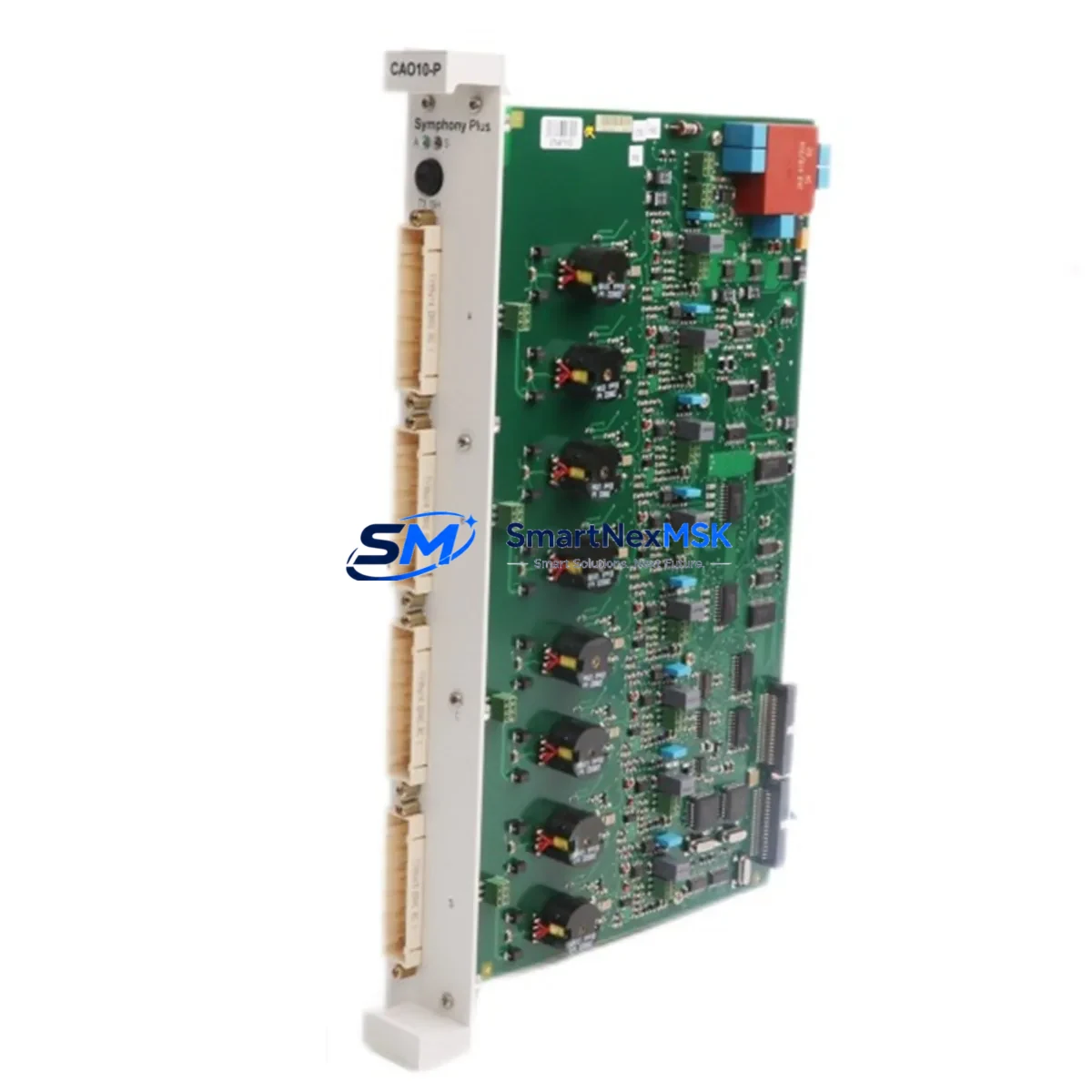
The ABB CAO10-P (part number 3BDH000723R1) is an analog output module designed for the ABB AC500 PLC platform — one of the most widely deployed modular programmable logic controller families in industrial automation. When this module fails or degrades, it directly impacts process control loops, actuator command signals, and closed-loop regulation across manufacturing, utilities, and infrastructure applications. Maintaining a verified replacement unit in your spare parts inventory is a proven strategy to minimize unplanned downtime and protect production continuity.
This listing provides an original ABB CAO10-P 3BDH000723R1 module, sourced from authorized supply channels, fully tested prior to shipment, and backed by a 12-month warranty. Each unit undergoes functional verification to confirm analog output accuracy, channel integrity, and communication handshake with the AC500 CPU before dispatch.
Spare Maintenance Table
| Parameter | Specification / Detail |
|---|---|
| Part Number | 3BDH000723R1 |
| Model | CAO10-P |
| Brand | ABB |
| Series | AC500 |
| Module Type | Analog Output Module |
| Output Channels | Typically 8 channels (current/voltage configurable per channel) |
| Output Signal | 0–10 V / 0–20 mA / 4–20 mA (channel-selectable) |
| Resolution | 12-bit or higher |
| Supply Voltage | 24 V DC (via AC500 backplane or terminal supply) |
| Backplane Compatibility | AC500 TB5xx / TB6xx expansion backplanes |
| Communication Interface | Internal AC500 S-Bus via backplane connector |
| Operating Temperature | 0 °C to +60 °C |
| Protection Class | IP20 |
| Country of Origin | Germany (DE) |
| Weight | 940 g |
| Condition | Original, new or tested-refurbished |
| Pre-shipment Test | Yes — functional output verification on all channels |
| Warranty | 12 Months |
| Delivery | Worldwide, DHL / FedEx / UPS express available |
Maintenance Planning for Continuous Operation
When a maintenance or procurement engineer schedules replacement of the CAO10-P 3BDH000723R1, the replacement event should be treated as a broader inspection opportunity for the surrounding control cabinet and signal chain. Analog output modules sit at the intersection of the PLC logic layer and the field device layer — a failure here can cascade into actuator faults, valve positioning errors, or drive speed reference loss.
During the same maintenance window, engineers should inspect the AC500 CPU module (PM5xx series) for firmware currency and battery status, as an outdated CPU firmware can cause compatibility issues with replacement I/O modules. The AC500 power supply module (PS5xx) should be checked for output voltage stability and ripple — degraded 24 V DC supply is a common root cause of intermittent analog output drift. If the cabinet uses a TB5xx or TB6xx expansion backplane, inspect the backplane connector pins and locking tabs for corrosion or mechanical wear before seating the new CAO10-P.
On the signal side, verify the analog output terminal blocks (typically Phoenix Contact or Weidmüller style) for loose ferrules and oxidized contacts. Signal cables running to frequency inverters, control valves, or positioners should be checked for shielding continuity — ungrounded shields are a frequent source of 4–20 mA loop noise after a module swap. If the system includes signal isolators or loop-powered barriers between the PLC output and field devices, confirm their input impedance is within the CAO10-P’s rated load range.
For systems using PROFIBUS DP or Modbus RTU communication modules alongside the CAO10-P, verify that the network termination resistors are correctly placed and that the communication module (e.g., AC500 CM572-DP PROFIBUS master) shows no fault LEDs after the I/O module replacement. In multi-rack configurations, also inspect the inter-rack communication cables and confirm rack addressing has not been disturbed during the physical swap.
Procurement engineers building a recommended spare parts kit around the CAO10-P should also consider stocking one unit each of the AC500 analog input module (CAI10-P or CAI18-P) and a digital output module (CD522 or CD522-XC) to cover the most common concurrent failure modes in mixed I/O cabinets. A spare 24 V DC fuse block or miniature circuit breaker rated for the I/O supply rail is also advisable.
Site Replacement Workflow
Replacing the CAO10-P 3BDH000723R1 on a live AC500 system follows a structured sequence to minimize downtime and avoid configuration loss:
1. Pre-replacement preparation: Export the current AC500 project from Automation Builder or PS501 Control Builder. Confirm the replacement module’s firmware version is compatible with the CPU firmware. Document the existing channel configuration (output type, range, scaling) from the engineering software before powering down.
2. Safe isolation: Place the process in manual or safe state at the DCS/SCADA level. De-energize the I/O supply rail feeding the CAO10-P using the dedicated MCB or fuse. Do not rely solely on the PLC’s software disable — physically isolate the 24 V DC supply to the module terminal block.
3. Module removal and installation: Release the backplane locking lever, slide out the faulty CAO10-P, and insert the replacement unit. Confirm the module clicks into the backplane connector fully. Re-energize the I/O supply rail and observe the module’s status LED — a solid green indicates successful backplane communication.
4. Configuration restore: In Automation Builder, perform an online comparison to verify the I/O configuration matches the replacement module’s channel count and type. Download any updated configuration if required. Confirm analog output values are tracking the PLC setpoints correctly using a calibrated loop calibrator or multimeter on each active channel.
5. Return to service: Release the process from manual mode, monitor the first 15–30 minutes of operation for any output drift or alarm, and update the maintenance log with the replacement date, module serial number, and test results. This documentation supports warranty claims and future lifecycle planning.
This workflow applies equally to planned preventive replacements and emergency corrective maintenance, and is compatible with hot-standby AC500 redundancy configurations where the redundant CPU takes over during the swap window.
Spare Parts Support FAQ
Q1: Is the CAO10-P 3BDH000723R1 compatible with all AC500 CPU generations?
The CAO10-P is designed for the AC500 V2 and V3 platform using TB5xx and TB6xx backplanes. Compatibility with specific CPU generations (PM554, PM564, PM573, PM591, PM592) depends on the backplane type and firmware version. We recommend confirming your CPU part number and firmware revision before ordering. Our technical team can assist with compatibility verification at no charge.
Q2: What testing is performed before shipment?
Every CAO10-P 3BDH000723R1 unit is functionally tested on an AC500 test bench prior to dispatch. Testing covers all analog output channels for correct signal range (0–10 V and 4–20 mA), backplane communication handshake, and LED status indication. A test report is available upon request for quality-critical applications.
Q3: What does the 12-month warranty cover?
The 12-month warranty covers manufacturing defects, functional failures under normal operating conditions, and DOA (dead-on-arrival) units. It does not cover damage caused by incorrect installation, overvoltage, or environmental conditions outside the module’s rated specifications. Warranty claims are processed within 5 business days of receiving the returned unit.
Q4: Can you support long-term supply for legacy AC500 systems?
Yes. We maintain stock of discontinued and hard-to-source ABB AC500 modules specifically to support legacy system life extension programs. If your facility operates older AC500 V1 or early V2 hardware, contact us with your full BOM and we will advise on availability, cross-reference options, and recommended stocking quantities to cover your planned maintenance cycles.
© 2026 SMARTNEXMSK. All rights reserved.
Original Source: https://smartnexmsk.com
Contact: sales@smartnexmsk.com | +86 18259474341


