ABB CBO10 Maintenance-Ready Spare for AC500 Automation
When a digital output module fails in an ABB AC500 PLC system, every minute of unplanned downtime translates directly into production loss. The ABB CBO10 is a 16-channel digital output module designed for the AC500 modular PLC platform — a workhorse component found in machine control panels, process automation cabinets, and utility infrastructure across manufacturing, energy, and water treatment sectors. Sourcing a verified, original CBO10 spare in advance is the single most effective step a maintenance engineer can take to protect system uptime and reduce mean time to repair (MTTR).
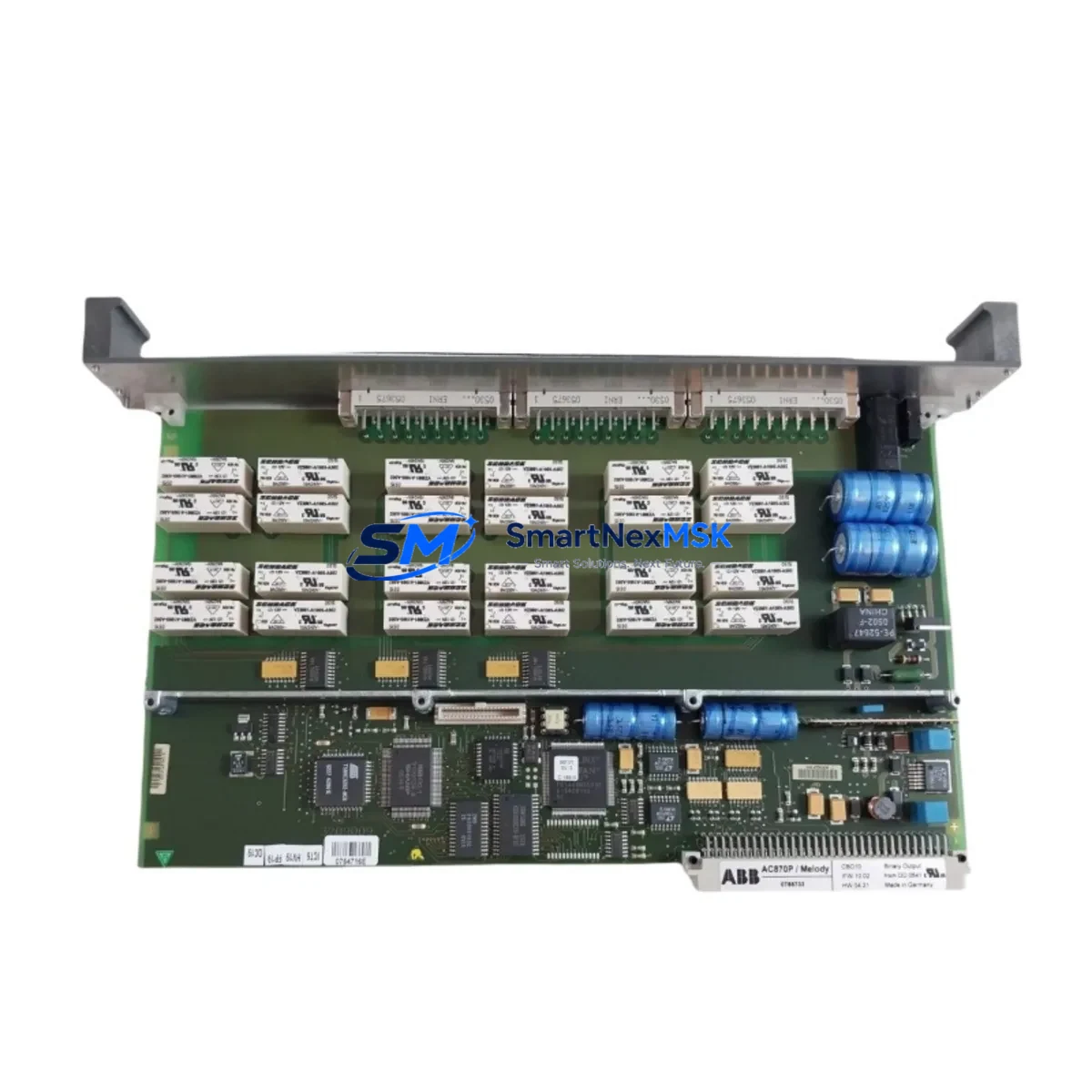
This listing supplies the ABB CBO10 as a maintenance-ready spare: inspected, function-tested prior to shipment, and backed by a 12-month warranty. Whether you are replenishing a depleted spare parts kit, replacing a failed module during a scheduled shutdown, or responding to an emergency fault, this unit ships promptly and arrives ready for direct installation into your AC500 rack.
Spare Maintenance Table
| Parameter | Specification / Detail |
|---|---|
| Part Number / SKU | CBO10 |
| Brand | ABB |
| Series | AC500 |
| Module Type | Digital Output Module |
| Number of Channels | 16 DO |
| Output Signal Type | 24 V DC transistor (source/sink, series-dependent) |
| Rated Output Current | 0.5 A per channel (typical) |
| Supply Voltage | 24 V DC (via backplane / terminal block) |
| Backplane Compatibility | AC500 CPU backplane (PM5xx / PM5xx-ETH series) |
| Mounting | Direct plug-in to AC500 I/O bus |
| Operating Temperature | -25 °C to +60 °C |
| Protection Rating | IP20 |
| Country of Origin | Germany |
| Weight | 240 g |
| Condition | Original, function-tested before shipment |
| Warranty | 12 Months |
| Certifications | CE, UL (AC500 platform) |
| Maintenance Application | Direct replacement for failed or degraded CBO10 in AC500 racks |
Maintenance Planning for Continuous Operation
A CBO10 replacement rarely occurs in isolation. Experienced maintenance engineers know that a digital output module failure is often symptomatic of broader stress in the control cabinet — and that a thorough inspection during the replacement window can prevent the next unplanned stop. When replacing the CBO10, the following components and subsystems should be evaluated concurrently:
Start with the 24 V DC power supply module feeding the AC500 rack. Voltage ripple or marginal current capacity is a leading cause of premature I/O module failure; verify output voltage under load and check capacitor age if the PSU is more than five years old. Next, inspect the AC500 CPU module (PM554 or PM591 series) — confirm firmware version compatibility with the CBO10 hardware revision and check for any logged diagnostic faults in the CPU’s event buffer.
Review the terminal blocks and field wiring connected to the CBO10’s output channels. Loose terminations, corroded contacts, or undersized conductors can cause intermittent output faults that are misdiagnosed as module failure. If the cabinet uses relay output expansion modules (such as the ABB CM582-DP or relay coupler boards) downstream of the CBO10, inspect coil drive circuits and contact wear simultaneously.
For systems using PROFIBUS-DP or Modbus RTU communication, verify that the communication interface module (e.g., CI590-CS31-HA or CI501-PNIO) is correctly parameterized after the CBO10 is swapped — some AC500 configurations require a hardware configuration download following any I/O module change. Check the CI module’s bus termination resistors and cable shielding integrity at the same time.
If the control cabinet includes signal isolators or loop-powered transmitters on the input side, verify that the corresponding digital input modules (CBI10 or CBI20) are reading correctly after the output module replacement — cross-channel interference from a shorted output can occasionally corrupt adjacent input readings. Inspect miniature circuit breakers (MCBs) and fuse holders protecting the 24 V output circuits; a nuisance trip or blown fuse on an output channel is a common precursor to module damage.
Finally, if the system includes an HMI panel (e.g., ABB CP600 series or a third-party touch panel) communicating with the AC500 CPU, confirm that all output status indicators on the HMI reflect the correct post-replacement state. Document the replacement in your CMMS and update the spare parts register to trigger reorder of a replacement CBO10 for the next maintenance cycle.
Site Replacement Workflow
Step 1 — Isolation and safety: Follow your site’s LOTO (Lockout/Tagout) procedure. De-energize the 24 V DC supply to the AC500 rack. Confirm zero voltage at the CBO10 terminal block before proceeding.
Step 2 — Module removal: Note the slot position of the CBO10 in the rack. Disconnect field wiring from the terminal block (photograph or label each wire before removal). Release the module locking tab and slide the CBO10 out of the backplane connector.
Step 3 — Visual inspection: Inspect the backplane connector pins for damage or contamination. Clean with dry compressed air if necessary. Check the adjacent modules for signs of heat stress or discoloration.
Step 4 — Spare installation: Insert the replacement CBO10 into the same slot. Ensure the module is fully seated and the locking tab engages. Reconnect field wiring in the correct terminal sequence. Verify terminal torque to manufacturer specification (typically 0.5–0.6 N·m for AC500 terminal blocks).
Step 5 — Power-up and verification: Re-energize the rack. Observe the CBO10 status LED — a steady green indicates normal operation. From the AC500 CPU (or connected programming tool), force each output channel individually and verify field-side response. Clear any residual fault codes in the CPU diagnostic log.
Step 6 — Documentation: Record the replacement date, failed module serial number, and replacement unit details. Update the spare parts inventory and schedule the next inspection interval. This workflow is compatible with both hot-standby and single-CPU AC500 configurations and minimizes total downtime to under 30 minutes for a prepared maintenance team.
Spare Parts Support FAQ
Q1: Is this CBO10 compatible with all AC500 CPU variants, including PM554 and PM591?
The CBO10 is designed for the AC500 I/O bus and is compatible with the full range of AC500 CPU modules (PM5xx series) that support standard digital I/O expansion. Compatibility with specific firmware versions should be confirmed against ABB’s hardware compatibility matrix for your CPU revision. If you are unsure, provide your CPU part number and we will advise before shipment.
Q2: What testing is performed before the CBO10 is shipped?
Each unit undergoes functional verification prior to dispatch: power-on self-test, channel-by-channel output switching test, and visual inspection of the backplane connector and terminal block. Units that do not pass all checks are not listed for sale. A 12-month warranty covers defects in materials and workmanship from the date of delivery.
Q3: How should I manage CBO10 stock levels for a multi-cabinet installation?
For facilities operating three or more AC500 racks with CBO10 modules, a minimum on-hand stock of one unit per four installed modules is a practical starting point. Review your historical MTBF data annually and adjust stock levels accordingly. For critical processes with zero-tolerance downtime, consider holding one spare per rack. We support long-term supply agreements and can reserve stock for scheduled annual shutdowns.
Q4: Can the CBO10 replace older or discontinued ABB digital output modules in legacy AC500 systems?
The CBO10 is the current-generation 16-channel digital output module for the AC500 platform and is the direct replacement for earlier variants with the same channel count and bus interface. For legacy systems using older I/O bus generations, physical and electrical compatibility should be verified before installation. Contact our technical team with your existing module part number and we will confirm interchangeability prior to order.
© 2026 SMARTNEXMSK. All rights reserved.
Original Source: https://smartnexmsk.com
Contact: sales@smartnexmsk.com | +86 18259474341


