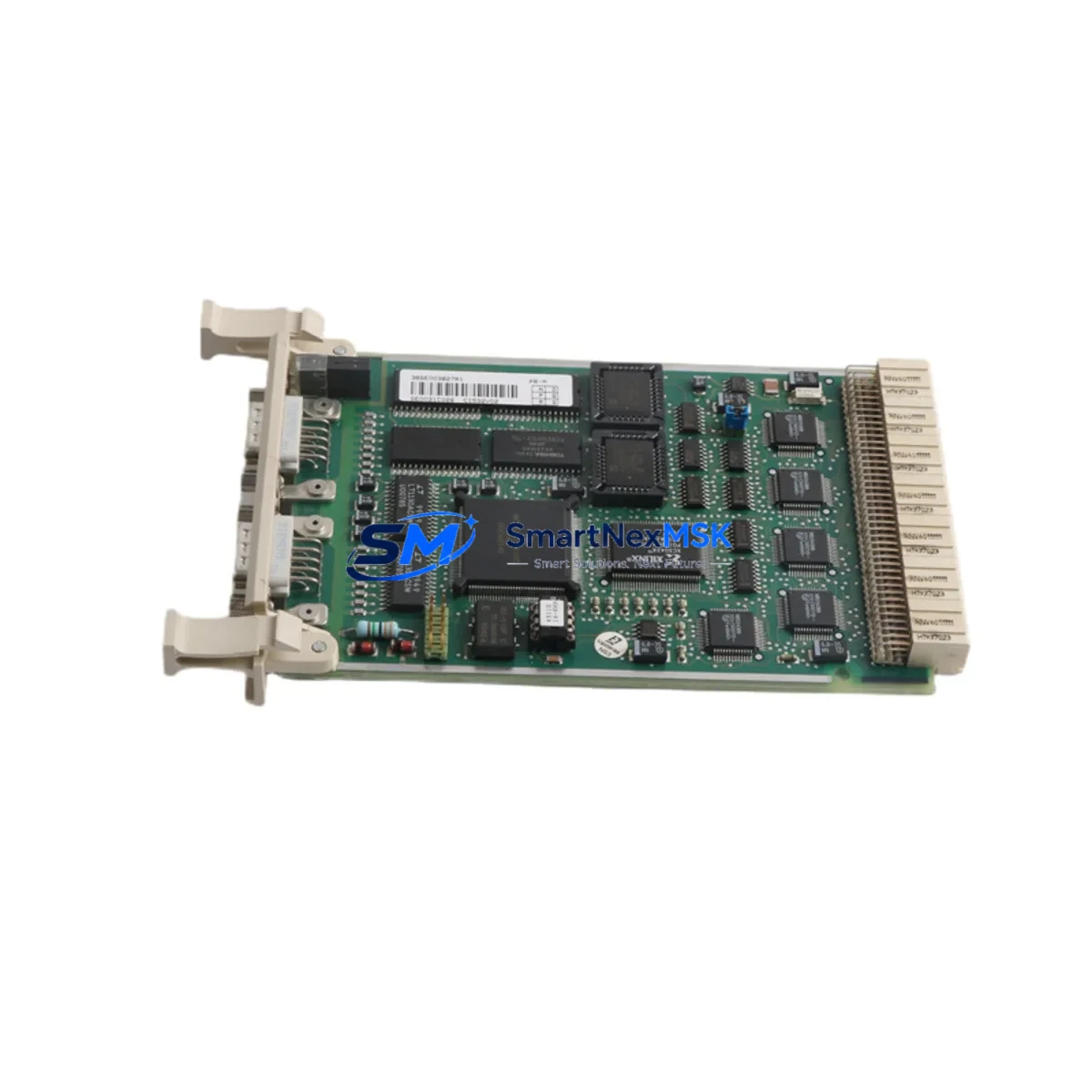
ABB CI532V02 3BSE003827R1 Retrofit-Ready Modbus Module for AC500 Control Systems
The ABB CI532V02 (catalog reference 3BSE003827R1) is a serial communication interface module designed for the ABB AC500 PLC platform, providing Modbus RTU and Modbus ASCII protocol support over RS-232 and RS-485 physical layers. As legacy AC500 installations age and original spare parts become increasingly difficult to source, the CI532V02 has become a critical retrofit component for engineers tasked with sustaining production continuity, upgrading communication infrastructure, or migrating from discontinued fieldbus architectures to modern serial-based supervisory networks.
This module slots directly into the AC500 CPU backplane alongside the PM5xx or PM5x3 processor modules, occupying a standard communication slot without requiring additional mounting hardware. Its compact DIN-rail-compatible form factor integrates cleanly into existing control cabinets, making it an ideal drop-in replacement for failed or end-of-life communication cards in running production lines. Before installation, engineers should verify the backplane slot assignment, confirm the module address configured in the PS501 Control Builder Plus programming environment, and review the existing Modbus master/slave role settings to ensure seamless handover without reprogramming the CPU logic.
Power supply compatibility is a key consideration during retrofit planning. The CI532V02 draws its operating voltage from the AC500 backplane bus, so the existing PM-E power supply module — typically a PM564 or PM583 variant — must have sufficient residual capacity to support the added communication load. In multi-slot configurations where I/O expansion modules such as the DC532 digital input/output module or the AX522 analog I/O module are already installed, a power budget review is strongly recommended before commissioning the replacement unit.
Upgrade Compatibility Table
| Parameter | CI532V02 (3BSE003827R1) |
|---|---|
| Compatible Platform | ABB AC500 (PM5xx / PM5x3 series) |
| Communication Protocol | Modbus RTU, Modbus ASCII |
| Physical Interface | RS-232, RS-485 |
| Slot Type | AC500 standard communication slot |
| Installation | DIN-rail, backplane-mounted |
| Programming Tool | PS501 Control Builder Plus |
| Replacement For | CI532V01, discontinued CI53x variants |
| Commissioning | Module address, baud rate, parity configuration required |
| Warranty | 12 months from date of shipment |
| Outgoing Test | Function-tested prior to dispatch |
Retrofit Planning for Existing Automation Systems
Successful integration of the CI532V02 into a legacy control system requires a structured pre-installation audit. Engineers should begin by documenting the existing wiring at the RS-485 terminal block, noting the A/B signal polarity, shield grounding method, and termination resistor placement — particularly in long-distance bus runs where impedance mismatches can cause communication errors after module swap. The replacement module uses the same 9-pin sub-D connector pinout as earlier CI53x variants, but terminal labeling differences between hardware revisions should be cross-checked against the current wiring diagram before energizing the bus.
In systems where the CI532V02 interfaces with a third-party SCADA or HMI — such as an ABB CP600 operator panel or a PC-based supervisory station running ABB Ability System 800xA — the Modbus register map and polling cycle must be validated post-replacement to confirm that all process variables are correctly mapped and that no address conflicts exist with other devices on the same serial segment. If the control cabinet also houses a CI590 PROFIBUS DP interface or a CI501 PROFINET module serving a parallel communication path, care must be taken to avoid slot conflicts and to maintain correct module sequencing in the Control Builder Plus hardware configuration tree.
For sites upgrading from older AC31 or AC100 controller generations, the CI532V02 provides a practical migration path when combined with a PM564 or PM573 CPU module. The Modbus driver function blocks available in the PS501 library — including the MBUS_MASTER and MBUS_SLAVE function blocks — can be adapted from legacy IEC 61131-3 code with minimal rework, preserving the core control logic while modernizing the communication layer. Existing HMI screens referencing Modbus holding registers typically require only address offset adjustments rather than full redesign.
Downtime Control During System Migration
Minimizing unplanned downtime during a communication module replacement requires preparation at three levels: hardware staging, software backup, and commissioning sequencing. Before removing the failed or obsolete CI532V02 from the backplane, a full project backup should be exported from PS501 Control Builder Plus and stored offline. The CPU should be placed in STOP mode only after confirming that all field devices on the Modbus segment are in a safe state and that any watchdog timers or safety interlocks have been appropriately bypassed or acknowledged per site safety procedures.
The replacement module should be pre-configured off-line — baud rate, parity, stop bits, and Modbus node address set to match the existing network parameters — so that the commissioning window is limited to physical installation, wiring verification, and a controlled CPU restart. In most AC500 retrofit scenarios, the total intervention window from module removal to verified communication restoration can be completed within 30 to 60 minutes, provided the replacement unit has been function-tested prior to dispatch. All CI532V02 units shipped by SMARTNEXMSK are tested under load conditions before packaging to eliminate infant-failure risk on site.
Retrofit Support FAQ
Q: Is the CI532V02 3BSE003827R1 a direct replacement for the CI532V01?
A: Yes. The CI532V02 is the current production revision of the CI532 series and is backward-compatible with CI532V01 installations. No hardware modification to the backplane or wiring is required; only the module address and communication parameters need to be confirmed in PS501 before restart.
Q: What commissioning steps are required after installing the replacement module?
A: After physical installation, open the hardware configuration in PS501 Control Builder Plus, verify the module is recognized in the correct slot, confirm baud rate and parity settings match the existing Modbus network, download the configuration to the CPU, and perform a communication test by monitoring live Modbus traffic from the SCADA or HMI station.
Q: Can the CI532V02 operate simultaneously with other communication modules in the same AC500 rack?
A: Yes. The AC500 backplane supports multiple communication modules in parallel slots. The CI532V02 can coexist with PROFIBUS, PROFINET, or Ethernet modules such as the CI590 or CI501, provided each module occupies a unique slot and is correctly addressed in the hardware configuration.
Q: What warranty and testing does SMARTNEXMSK provide with this module?
A: Every CI532V02 3BSE003827R1 unit is function-tested prior to shipment and covered by a 12-month warranty from the date of delivery. In the event of a confirmed defect within the warranty period, SMARTNEXMSK will arrange replacement or repair at no additional cost to the buyer.
© 2026 SMARTNEXMSK. All rights reserved.
Original Source: https://smartnexmsk.com
Contact: sales@smartnexmsk.com | +86 18259474341


