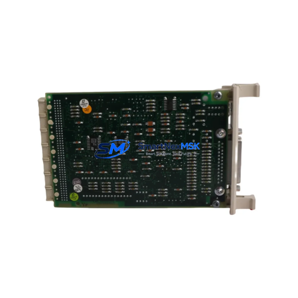
ABB CI570 3BSE001440R1 Retrofit-Ready PROFIBUS DP Master for AC800M Control Systems
The ABB CI570 (part number 3BSE001440R1) is a PROFIBUS DP Master communication module designed for integration within the ABB AC800M Modular Controller platform. As legacy automation infrastructure ages and original spare parts become increasingly difficult to source, the CI570 3BSE001440R1 has become one of the most sought-after retrofit and replacement components for engineers managing aging DCS and PLC architectures across process industries, power generation, and discrete manufacturing.
Whether you are replacing a failed unit on an active production line, upgrading a control cabinet from an older AC800M revision, or migrating a PROFIBUS DP network to a more maintainable configuration, the CI570 provides a direct, wiring-compatible solution that minimizes engineering rework and reduces total downtime exposure. Each unit supplied by SMARTNEXMSK is sourced from verified channels, subjected to functional pre-shipment testing, and backed by a 12-month warranty covering hardware defects under normal operating conditions.
Upgrade Compatibility Table
| Parameter | Details |
|---|---|
| Module SKU | CI570 / 3BSE001440R1 |
| Compatible Platform | ABB AC800M (PM861, PM864, PM866, PM891 controllers) |
| Communication Protocol | PROFIBUS DP (IEC 61158), Master Class 1 & 2 |
| Backplane Interface | AC800M module bus via TB820V2 or TB840A termination board |
| Installation Requirement | Slots 1–7 on AC800M CPU rack; no additional power module required for single-slot use |
| Wiring Compatibility | Direct replacement for CI570 variants; standard DB9 PROFIBUS connector |
| Replacement Recommendation | Suitable direct replacement for discontinued CI570 units; verify firmware revision with PM8xx controller |
| Commissioning Notes | Module address must be configured via Control Builder M; GSD file upload required for slave devices |
| Warranty | 12 months from shipment date, covering hardware defects under normal use |
Retrofit Planning for Existing Automation Systems
Successful integration of the CI570 3BSE001440R1 into an existing control architecture requires a structured pre-replacement assessment. Before removing the failed or end-of-life module, engineers should document the current PROFIBUS network topology, including the number of slave devices, their GSD configurations, and the DP address assignments already in use. This information is critical for restoring communication links without triggering process alarms or causing unintended actuator responses during the cutover window.
On the hardware side, confirm that the AC800M rack — typically a TB820V2 or TB840A termination board assembly — has an available slot in positions 1 through 7. If the rack is fully populated, a rack expansion using an additional AC800M module carrier may be necessary before the CI570 can be installed. Power budget verification is equally important: the CI570 draws from the rack’s internal 5 VDC bus, and the total current consumption of all installed modules, including the PM864 or PM866 processor module, S800 I/O modules connected via the module bus, and any CI854 or CI857 fieldbus communication modules sharing the same rack, must remain within the power supply unit’s rated output.
For sites running mixed fieldbus environments, the CI570 coexists with other communication modules such as the CI854A (FOUNDATION Fieldbus HSE) or CI857 (PROFINET IO) without conflict, provided each module occupies a dedicated slot and the Control Builder M project is updated to reflect the new hardware configuration. If the legacy system also includes an older CI532V02 or CI535V26 PROFIBUS module from a previous AC800M generation, the CI570 is the recommended upgrade path, offering improved diagnostic capabilities and broader GSD compatibility.
Termination resistors on the PROFIBUS segment must be verified before powering up the new module. In long cable runs or high-node-count networks, improper termination is a leading cause of intermittent communication faults that can be misdiagnosed as module failures. Ensure that only the first and last physical devices on the PROFIBUS segment have termination enabled, and that cable shielding is grounded at a single point to prevent ground loops. Once the CI570 is seated and the termination board is secured, the module will appear in the Control Builder M hardware tree and can be configured with the appropriate DP master parameters before going online.
Downtime Control During System Migration
Minimizing production interruption during a PROFIBUS module replacement requires careful sequencing of both the hardware swap and the software restoration steps. The recommended approach is to perform a full backup of the AC800M application program using Control Builder M before any physical work begins. This backup captures the current function block diagram, signal lists, and communication object configurations, ensuring that the restored program is byte-for-byte identical to the running version.
Where process conditions allow, consider placing the affected control loops in manual mode at the DCS operator station or HMI — whether running ABB’s 800xA System, a third-party SCADA, or a standalone Panel 800 operator panel — before initiating the module swap. This prevents automatic control actions from responding to the temporary loss of PROFIBUS I/O data during the changeover. Field devices connected to the PROFIBUS segment, such as Siemens ET 200S distributed I/O stations, ABB TZID-C positioners, or Endress+Hauser Promag flowmeters, will hold their last valid output states during the communication interruption, provided their fail-safe configurations are set appropriately.
After the CI570 3BSE001440R1 is installed and the Control Builder M project is downloaded to the PM8xx controller, allow the PROFIBUS network to complete its initialization cycle — typically 10 to 30 seconds depending on the number of slaves — before returning control loops to automatic mode. Verify that all slave devices are reporting green status in the PROFIBUS diagnostic view and that process values are updating at the expected scan rate before signing off on the migration. This structured approach consistently achieves total cutover times of under 45 minutes for single-module replacements, keeping unplanned downtime within acceptable maintenance windows.
Retrofit Support FAQ
Q1: Is the CI570 3BSE001440R1 a direct drop-in replacement for my existing CI570 unit?
Yes. The CI570 3BSE001440R1 is the standard catalog part number for the CI570 PROFIBUS DP Master module and is physically and electrically compatible with all AC800M racks that support this module family. No wiring changes to the termination board or PROFIBUS cable are required. You will need to download the existing Control Builder M project to the new module after installation to restore communication parameters.
Q2: What commissioning steps are required after installing the replacement module?
After seating the CI570 in the rack, open Control Builder M and verify that the module appears correctly in the hardware configuration tree. Confirm that the PROFIBUS DP master address and baud rate settings match the previous configuration. If any slave GSD files were customized, re-upload them to the master configuration. Perform a full download to the controller and monitor the PROFIBUS diagnostic view to confirm all slaves are communicating before returning the system to automatic operation.
Q3: Can the CI570 operate alongside other communication modules in the same AC800M rack?
Yes. The CI570 can coexist with other modules such as the CI854A (FOUNDATION Fieldbus), CI857 (PROFINET IO), and standard S800 I/O modules within the same AC800M rack, subject to available slot count and rack power budget. Each communication module operates independently on the module bus and is addressed separately within the Control Builder M project.
Q4: What does the 12-month warranty cover, and how does pre-shipment testing work?
Every CI570 3BSE001440R1 unit shipped by SMARTNEXMSK undergoes functional pre-shipment testing to verify PROFIBUS communication initialization, module bus recognition, and power-on self-diagnostics. The 12-month warranty covers hardware defects arising under normal operating conditions from the date of shipment. Units that fail within the warranty period are replaced or refunded. Warranty does not cover damage resulting from incorrect installation, overvoltage, or environmental conditions outside the module’s rated specifications.
© 2026 SMARTNEXMSK. All rights reserved.
Original Source: https://smartnexmsk.com
Contact: sales@smartnexmsk.com | +86 18259474341


