ABB CI854AK01 3BSE030220R1 Retrofit-Ready PROFIBUS DP Module for AC 800M Control Systems
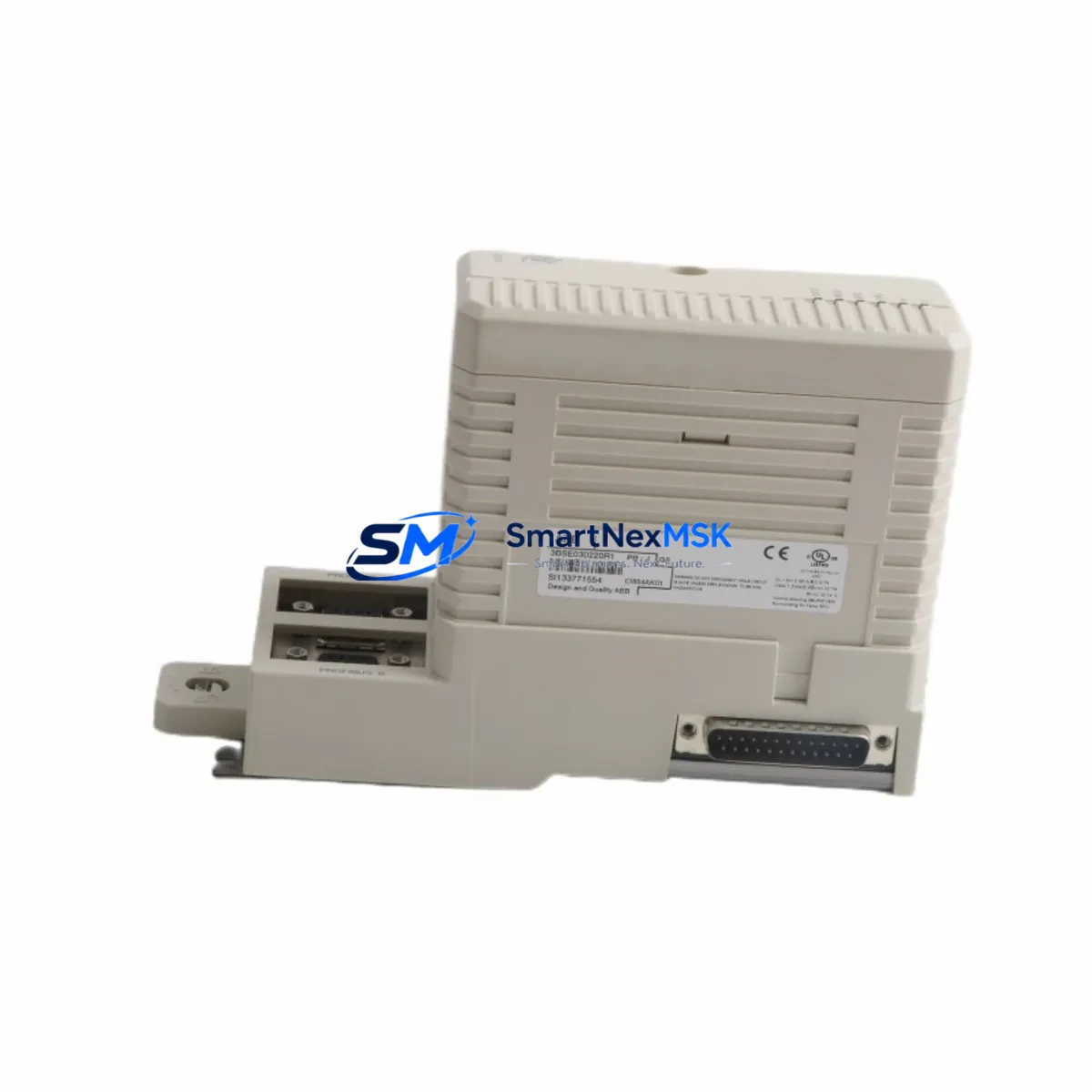
The ABB CI854AK01 (part number 3BSE030220R1) is a PROFIBUS DP communication module engineered for the AC 800M Distributed Control System platform. As legacy automation infrastructure ages and OEM support windows close, the CI854AK01 has become one of the most sought-after retrofit and replacement components in process industries, power generation, oil & gas, and chemical manufacturing. Whether you are replacing a failed unit, upgrading a discontinued module, or migrating an entire control cabinet to a more maintainable architecture, the CI854AK01 delivers the compatibility, reliability, and field-proven performance that industrial engineers demand.
This module slots directly into the AC 800M controller rack — typically alongside the PM861AK01 or PM864AK01 processor modules — and communicates over the PROFIBUS DP protocol at speeds up to 12 Mbit/s. It supports up to 125 slave devices per segment, making it suitable for large-scale I/O expansions involving remote I/O stations, variable frequency drives, intelligent field devices, and third-party PROFIBUS-compatible equipment. The CI854AK01 is fully compatible with the S800 I/O family, including AI810, AO810, DI810, and DO810 modules, which are commonly retained during partial retrofits to reduce rewiring costs.
Upgrade Compatibility Table
| Parameter | CI854AK01 / 3BSE030220R1 |
|---|---|
| Compatible Controller | AC 800M (PM861, PM864, PM866, PM891) |
| Communication Protocol | PROFIBUS DP V0 / V1 / V2 |
| Max Bus Speed | 12 Mbit/s |
| Max Slave Devices | 125 per segment |
| Backplane Interface | AC 800M module bus (standard rack slot) |
| Installation | Direct rack insertion — no adapter required |
| Replaces / Supersedes | CI854A (3BSE025255R1), CI854B (3BSE030220R1 variants) |
| Wiring Compatibility | Standard DB9 PROFIBUS connector — existing cable reusable |
| Firmware / Software | Compatible with Control Builder M (CBM) 5.x and later |
| Commissioning Tool | ABB Control Builder M, PROFIBUS configuration tool |
| Warranty | 12 Months — covers hardware defects and functional failure |
Retrofit Planning for Existing Automation Systems
Successful retrofit of the CI854AK01 into an existing AC 800M system requires a structured pre-installation review. Engineers should begin by auditing the current rack configuration: confirm the available module slot position, verify that the rack’s internal bus is not saturated, and check the power supply capacity of the installed PM861AK01 or PM864AK01 processor. The CI854AK01 draws power from the rack backplane, and systems running near the maximum load of the SD821 or SD822 power supply modules should be evaluated before adding communication capacity.
Terminal wiring for the PROFIBUS DP segment typically uses a standard 9-pin D-sub connector. In most retrofit scenarios, the existing PROFIBUS cable — shielded twisted pair, typically Belden 3079A or equivalent — can be reused without modification, provided the cable length and termination resistors are within specification. Confirm that the first and last devices on the PROFIBUS segment have active termination enabled, and that intermediate nodes have termination disabled to prevent signal reflection.
Module addressing is configured through Control Builder M. When replacing a failed CI854AK01, the replacement module inherits the same module address and PROFIBUS master configuration from the project file, provided the hardware address switch on the module is set identically to the original. Engineers should document the existing switch position before removal. If the original module address is unknown, it can be retrieved from the CBM project archive or from the AC 800M controller’s diagnostic log via the built-in web server interface.
For systems that also include CI801 or CI840A communication modules handling Modbus TCP or FOUNDATION Fieldbus segments, the CI854AK01 retrofit does not affect those communication paths. Each communication module operates independently on the AC 800M module bus. However, if the retrofit is part of a broader migration — for example, consolidating multiple legacy racks into a single updated cabinet — engineers should also review the TB820V2 ModuleBus Optical Port and any associated S800 remote I/O clusters to ensure the optical fiber links remain within distance limits.
HMI integration should be verified after module replacement. Systems using ABB’s 800xA Extended Automation platform or third-party SCADA systems connected via OPC DA/UA should confirm that the PROFIBUS slave device list in the HMI configuration matches the physical network. If slave GSD files were previously imported into the PROFIBUS master configuration, they are stored in the CBM project and do not need to be re-imported for a like-for-like module swap. For systems using Panel 800 operator terminals or PP865 panels, no HMI screen modifications are required for a direct replacement.
Downtime Control During System Migration
Minimizing unplanned downtime is the primary concern during any live-system retrofit. For the CI854AK01, the recommended approach is a hot-standby swap where the AC 800M system supports redundant communication modules. In non-redundant configurations, the PROFIBUS segment will be offline during the physical swap — typically less than five minutes for an experienced technician. To protect the original control logic, export and archive the full CBM project before beginning any hardware work. The AC 800M controller retains its application program in non-volatile memory, so a power cycle during the swap does not result in program loss.
Before removing the failed module, place the affected PROFIBUS slaves in a safe state — either through the process control system’s manual override functions or by coordinating with the field operations team to hold process variables at their last known good values. After inserting the CI854AK01 replacement, the controller will automatically re-establish communication with all configured PROFIBUS slaves within the scan cycle defined in the CBM project. Verify slave status in the CBM online diagnostic view and confirm that all I/O signals — including those from S800 AI810 analog input modules and DO810 digital output modules — are reading correctly before releasing the process back to automatic control.
For migrations involving protocol changes — for example, replacing a legacy CI854A with the CI854AK01 while simultaneously migrating some field devices from PROFIBUS DP to PROFIBUS PA — a phased approach is recommended. Complete the PROFIBUS DP segment restoration first, validate all signals, then proceed with the PA segment work using the appropriate DP/PA coupler. This approach ensures that the core control loop remains operational throughout the migration window.
Retrofit Support FAQ
Q1: Is the CI854AK01 (3BSE030220R1) a direct drop-in replacement for the CI854A (3BSE025255R1)?
Yes. The CI854AK01 is the current production successor to the CI854A and is mechanically and electrically compatible with the same rack slot. The PROFIBUS DP connector pinout is identical, and the module address switch positions are equivalent. No wiring changes are required. The CBM project file does not need to be modified for a like-for-like swap.
Q2: What commissioning steps are required after installing the CI854AK01?
After physical installation, power on the rack and observe the module’s LED status indicators. The RUN LED should illuminate green within 30 seconds as the module initializes and the AC 800M controller loads the PROFIBUS master configuration. Use Control Builder M’s online diagnostic view to verify that all configured slave devices are in the DATA_EXCHANGE state. If any slave shows a fault, check the PROFIBUS cable termination, verify the slave’s station address, and confirm the GSD file version matches the installed slave firmware.
Q3: Can the CI854AK01 be used in a system that also has CI840A FOUNDATION Fieldbus modules installed?
Yes. The CI854AK01 and CI840A operate on separate communication buses and do not interfere with each other. Both modules can coexist in the same AC 800M rack. Each module is independently configured in Control Builder M and communicates with its respective field devices without cross-dependency.
Q4: What does the 12-month warranty cover, and what is the shipping and testing process?
Every CI854AK01 unit shipped by SMARTNEXMSK undergoes pre-shipment functional testing, including power-on verification, LED status check, and communication port continuity testing. The 12-month warranty covers hardware defects and functional failure under normal operating conditions. Units are shipped with anti-static packaging and include a test report. Expedited shipping is available for urgent retrofit and breakdown situations. Contact our technical team to confirm lead time and stock availability before placing your order.
© 2026 SMARTNEXMSK. All rights reserved.
Original Source: https://smartnexmsk.com
Contact: sales@smartnexmsk.com | +86 18259474341


