ABB CP502 1SBP260190R1001-A Retrofit-Ready Text Display for AC500 Control Systems
The ABB CP502 (Part No. 1SBP260190R1001-A) is a compact text display panel engineered for seamless integration into ABB AC500 PLC control systems. As legacy HMI panels reach end-of-life and original ABB CP500 series displays become increasingly difficult to source, the CP502 serves as the definitive retrofit-ready replacement — preserving existing wiring infrastructure, communication links, and operator interface logic while delivering a reliable upgrade path for aging automation architectures.
Whether you are modernizing a paper mill drive control cabinet, upgrading a water treatment SCADA panel, or restoring a discontinued production line, the CP502 provides the compatibility and field-proven reliability that industrial maintenance engineers demand. It is fully compatible with the ABB AC500 CPU modules including the PM554-T, PM564-T, and PM583-ETH, and integrates directly with the AC500 backplane bus without requiring additional interface adapters.
Upgrade Compatibility Table
| Parameter | Details |
|---|---|
| Part Number | 1SBP260190R1001-A |
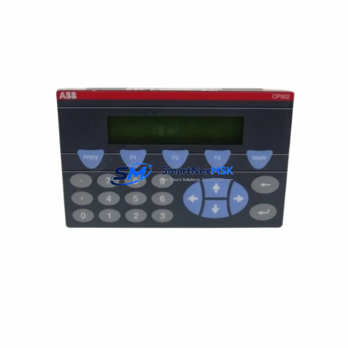
| Model | ABB CP502 |
| Compatible PLC Series | ABB AC500 (PM554, PM564, PM572, PM583, PM591, PM592) |
| Replaces / Supersedes | CP501, CP500 series legacy text panels |
| Display Type | Text LCD, 4-line × 20-character |
| Communication Interface | AC500 internal bus (direct backplane mount) |
| Installation | DIN rail / panel door mount; standard AC500 slot |
| Power Supply | Supplied via AC500 CPU or power supply module (PS501, PS502) |
| Programming Tool | Automation Builder / PS501 Control Builder Plus |
| Retrofit Wiring Change | None required — direct plug-in replacement on AC500 rack |
| Commissioning Requirement | Address assignment via Automation Builder; HMI screen re-mapping may apply |
| Warranty | 12 Months — covers manufacturing defects, functional failure, and DOA units |
Retrofit Planning for Existing Automation Systems
Replacing a legacy CP501 or CP500 text panel with the CP502 in an operational AC500 control system requires a structured pre-migration checklist. Before removing the existing panel, engineers should document all active HMI screen definitions, variable bindings, and alarm text strings stored in the original project file within PS501 Control Builder Plus or Automation Builder. These screen objects must be re-validated against the CP502’s display buffer and character set to ensure no truncation occurs during migration.
Power budget verification is a critical first step. The CP502 draws its operating power directly from the AC500 CPU module or from a dedicated PS501 or PS502 power supply module mounted on the same rack. If the existing rack is already near its power budget ceiling — particularly in dense configurations using multiple AI523 analog input modules, DI524 digital input modules, or AO523 analog output modules — a power audit must be completed before installation to avoid brownout conditions on the backplane bus.
Terminal wiring for the CP502 is handled entirely through the AC500 backplane connector, so no external terminal block rewiring is required. However, if the legacy installation used an external RS-232 or RS-485 serial link to a standalone HMI terminal, engineers should verify whether that communication path is being retired or migrated to an Ethernet-based HMI solution. In modernization projects where a full HMI upgrade is planned, the CP502 is often deployed as an interim operator interface while a new CP635 or CP651 color touch panel is commissioned on a parallel Ethernet segment.
Module address configuration is performed in Automation Builder by assigning the CP502 to the correct slot position on the AC500 rack. In multi-rack configurations using TB521-ETH or TB541-ETH expansion bus couplers, the display module address must be consistent with the rack topology defined in the PLC program. Failure to match the slot address will result in a configuration fault on the CPU, which can be diagnosed via the PM583-ETH diagnostic LED array or through the Automation Builder online monitoring interface.
For sites running Modbus RTU or PROFIBUS DP communication stacks alongside the AC500 CPU, the CP502 installation does not affect those protocol layers. Communication modules such as the CM572-DP PROFIBUS master or CM589-PNIO PROFINET IO adapter continue to operate independently on the backplane, and no protocol reconfiguration is required as part of the CP502 retrofit.
Downtime Control During System Migration
Minimizing unplanned downtime is the primary operational concern during any CP502 retrofit. The recommended approach is a hot-swap preparation protocol: before the maintenance window, pre-configure the replacement CP502 offline using Automation Builder with the same project file used on the existing system. Load the HMI screen definitions, variable tags, and alarm messages into the new module’s configuration, and verify the project compiles without errors against the target CPU firmware version.
During the maintenance window, the AC500 CPU should be placed in STOP mode before the legacy panel is physically removed. This prevents spurious I/O state changes from propagating to field devices during the swap. The CPU’s retain memory — which holds critical process variables, counters, and timer states — is preserved in the CPU module itself and is not affected by the panel replacement. After the CP502 is seated and the rack is powered, the CPU can be returned to RUN mode, and the HMI screens should be validated against live process values within the first five minutes of operation.
For continuous-process industries where even a brief STOP mode is unacceptable, the CP502 can be installed on a secondary rack slot while the legacy panel remains active, allowing parallel validation before the final cutover. This approach requires a temporary dual-panel configuration in the Automation Builder project, which can be reverted once the CP502 is confirmed operational. All shipped units undergo functional power-on testing and display verification prior to dispatch, reducing the risk of DOA failures during critical maintenance windows.
Retrofit Support FAQ
Q1: Is the CP502 (1SBP260190R1001-A) a direct drop-in replacement for the CP501?
Yes. The CP502 uses the same AC500 backplane slot interface as the CP501 and CP500 series panels. No external wiring changes are required. HMI screen projects created for the CP501 in PS501 Control Builder Plus will require re-import and re-validation in Automation Builder, as the project file format differs between generations. Variable bindings and alarm text strings are preserved during migration with minor manual adjustments.
Q2: What commissioning steps are required after installing the CP502?
After physical installation, open the Automation Builder project and assign the CP502 to the correct rack slot in the hardware configuration tree. Download the updated configuration to the CPU via USB programming cable or Ethernet. Verify that the CP502 appears online in the device tree without configuration faults. Cycle through all HMI screens to confirm variable display accuracy, and test all operator input keys for correct function mapping. The full commissioning sequence typically takes 30–60 minutes for a standard single-rack AC500 system.
Q3: Can the CP502 operate with AC500 CPUs running older firmware versions?
The CP502 is compatible with AC500 CPU firmware versions from V2.x onwards. For CPUs running firmware below V2.0 — typically found on early PM554 or PM564 units installed before 2010 — a firmware update is strongly recommended before deploying the CP502. Firmware updates are performed via the USB port on the CPU front face using Automation Builder’s firmware update wizard. Always back up the existing PLC program before initiating a firmware update.
Q4: What does the 12-month warranty cover, and how is a warranty claim processed?
The 12-month warranty covers all manufacturing defects, functional failures under normal operating conditions, and dead-on-arrival (DOA) units confirmed within 30 days of receipt. Warranty claims are initiated by contacting our sales team with the order reference number and a description of the fault. For DOA claims, we dispatch a replacement unit within 2 business days upon fault confirmation. For field failures within the warranty period, units are repaired or replaced at no charge. The warranty does not cover damage resulting from incorrect installation, overvoltage events, or unauthorized modification.
© 2026 SMARTNEXMSK. All rights reserved.
Original Source: https://smartnexmsk.com
Contact: sales@smartnexmsk.com | +86 18259474341


