ABB DC522 1SAP240600R0001 Retrofit-Ready Digital I/O for AC500 Control Systems
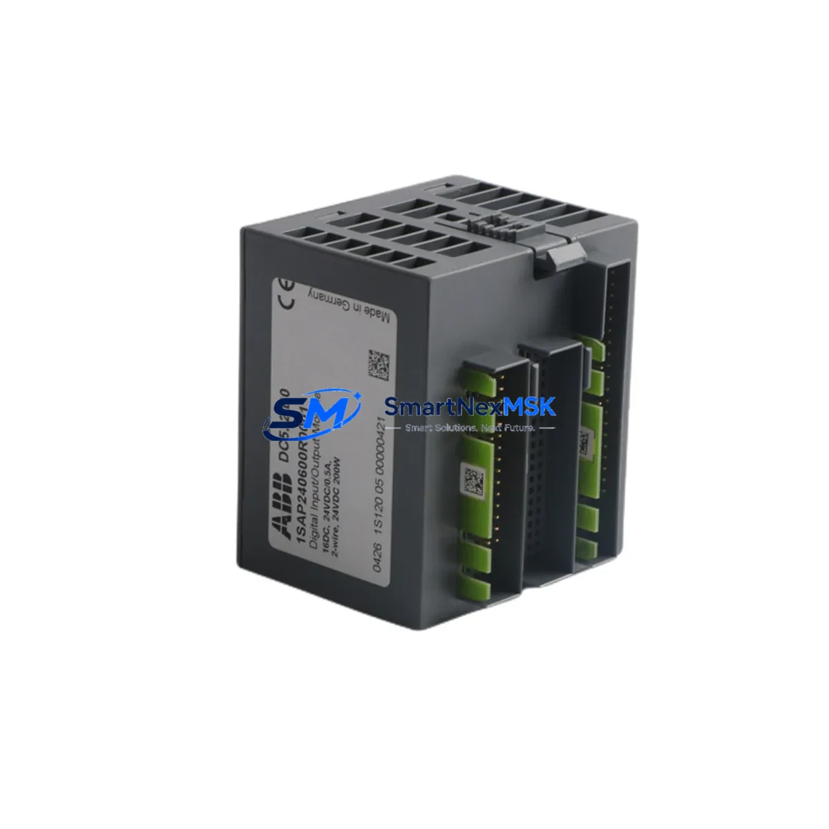
The ABB DC522 (1SAP240600R0001) is a 32-point digital input/output module engineered for the ABB AC500 PLC platform. Designed to serve as a direct, wiring-compatible replacement for aging or discontinued I/O modules in existing AC500 control architectures, the DC522 enables plant engineers and system integrators to modernize legacy automation panels without redesigning the entire control cabinet or rewriting established ladder logic programs.
Whether you are replacing a failed module in a running production line, upgrading an obsolete I/O tier in a distributed control system, or expanding I/O capacity during a phased retrofit, the DC522 slots directly into the AC500 TB521, TB522, or TB523 terminal base, preserving existing field wiring and eliminating the need for new cable harnesses. Each unit is pre-tested against ABB factory specifications and ships with a 12-month warranty from date of invoice.
Upgrade Compatibility Table
| Parameter | DC522 1SAP240600R0001 | Notes / Retrofit Guidance |
|---|---|---|
| I/O Points | 32 DI/DO (configurable) | Matches DC521 / DC523 channel count in most AC500 rack layouts |
| Terminal Base Compatibility | TB521, TB522, TB523 | No rewiring required when replacing same-series terminal base |
| Backplane Interface | AC500 internal bus | Compatible with PM571, PM572, PM581, PM582, PM591, PM592 CPUs |
| Supply Voltage | 24 V DC (via terminal base) | Verify PS501 or PS502 power supply capacity before installation |
| Communication Protocol | AC500 internal I/O bus | No additional fieldbus configuration required for local rack modules |
| Module Address | Auto-assigned by CPU | Confirm slot address in Automation Builder / PS501 project file |
| Replacement Candidates | DC521, DC523, DC531, DC532 | Verify I/O type (sink/source) and channel grouping before swap |
| Debugging Tool | Automation Builder 2.x / PS501 | Use online monitoring to verify I/O mapping post-installation |
| Warranty | 12 Months | Covers manufacturing defects; includes pre-shipment functional test |
Retrofit Planning for Existing Automation Systems
Successful integration of the DC522 into a legacy AC500 system begins with a thorough audit of the existing control cabinet. Before removing the failed or obsolete module, engineers should document the current terminal base model (TB521, TB522, or TB523), confirm the 24 V DC power supply — typically a PS501 or PS502 — has sufficient current headroom for the replacement module, and photograph all field wiring connections for reference during recommissioning.
The DC522 occupies a standard AC500 rack slot. In multi-rack configurations using an AC500 expansion rack with TA526 or TA527 bus adapters, the module address is automatically resolved by the CPU during startup. Engineers should open the existing Automation Builder project and verify that the hardware configuration tree reflects the correct slot assignment. If the project was originally developed under PS501 Control Builder Plus, the same hardware tree structure applies — no migration of the program logic is required.
For systems that include CM572-DP PROFIBUS DP communication modules or CM577-ETH Ethernet communication modules in the same rack, the DC522 installation does not affect fieldbus addressing. PROFIBUS node addresses and Ethernet IP settings remain unchanged, as these are managed by the communication module independently of local I/O modules. However, if the retrofit involves migrating from a PROFIBUS-based remote I/O tier to a local rack I/O configuration, engineers must update the GSD file references and re-map the I/O variables in the CPU program.
In control cabinets where HMI panels such as the CP635 or CP651 are connected via Modbus TCP or OPC UA, the HMI screen variable bindings should be reviewed after the I/O module swap. Since the DC522 preserves the same I/O address structure as its predecessors, most HMI screens will not require modification — but a full screen-by-screen verification during commissioning is recommended to confirm that all digital status indicators and control buttons map correctly to the new module’s channel assignments.
When the retrofit involves replacing multiple I/O modules across a rack — for example, swapping both a DC522 and an AX522 analog I/O module simultaneously — it is advisable to perform the replacement one module at a time, cycling power between each swap and verifying I/O response before proceeding to the next module. This staged approach isolates any wiring or configuration issues to a single module and significantly reduces diagnostic time during commissioning.
For systems using programming cables such as the TK501 USB programming cable or direct Ethernet connection to the CPU, ensure the Automation Builder laptop is connected and the project is in online monitoring mode before and after the module swap. This allows real-time verification of I/O status bits and confirms that the replacement DC522 is recognized by the CPU without requiring a full cold restart of the control system.
Downtime Control During System Migration
Minimizing unplanned downtime is the primary concern in any live-system I/O module replacement. The DC522’s plug-and-play compatibility with the AC500 terminal base system means that field wiring remains undisturbed during the module swap — the terminal base stays mounted in the cabinet, and only the module itself is extracted and replaced. This design reduces the physical swap time to under five minutes in most installations.
To protect the original program logic, always create a full backup of the Automation Builder project — including the hardware configuration, program blocks, variable tables, and HMI project files — before beginning any hardware change. Store the backup on a separate device, not only on the engineering laptop. If the CPU is a PM592 or later model with onboard SD card support, use the SD card backup function to create a complete system snapshot that can be restored in under two minutes if an unexpected fault occurs during commissioning.
For production lines where even a brief interruption is critical, consider pre-configuring the replacement DC522 offline using a spare rack and terminal base, verifying its I/O response in a bench test environment before bringing it to the production floor. This pre-staging approach, combined with a documented wiring checklist and a step-by-step commissioning procedure, consistently reduces total migration downtime to under 30 minutes — including power cycling, module recognition, I/O verification, and HMI confirmation.
All DC522 units supplied by SMARTNEXMSK undergo a pre-shipment functional test that verifies channel-by-channel I/O response, backplane communication integrity, and power consumption within ABB specification limits. Each unit ships with a test report and is covered by a 12-month warranty from the date of invoice, ensuring that your retrofit investment is protected from the moment the module arrives on site.
Retrofit Support FAQ
Q1: Is the DC522 1SAP240600R0001 a direct drop-in replacement for the DC521 or DC523?
In most AC500 installations, yes. The DC522 uses the same TB521/TB522/TB523 terminal base family and the same backplane interface as the DC521 and DC523. However, you should verify the I/O channel type (sink vs. source configuration) and the number of channel groups in your existing hardware configuration before swapping, as these parameters affect wiring polarity and program variable mapping.
Q2: Do I need to modify my Automation Builder program after installing the DC522?
In most cases, no program modification is required if you are replacing a module of the same type and slot position. The CPU will recognize the DC522 automatically on the next power cycle. If the replacement involves a different module type or a different slot, you will need to update the hardware configuration tree in Automation Builder and re-download the project to the CPU.
Q3: What wiring checks should I perform before powering up after the module swap?
Verify that all field wiring terminals on the terminal base are securely fastened and that no wires were disturbed during the module extraction. Confirm that the 24 V DC supply to the terminal base is within the 20.4–28.8 V DC operating range. Check that the module is fully seated on the terminal base and that the locking lever is engaged. Then power up and use Automation Builder online monitoring to verify that all I/O channels report the expected states before resuming production.
Q4: What does the 12-month warranty cover, and how is it claimed?
The 12-month warranty covers manufacturing defects and functional failures under normal operating conditions. Each unit is pre-tested before shipment and ships with a functional test report. To claim warranty service, contact SMARTNEXMSK with the invoice number and a description of the fault. We will arrange a replacement unit or repair, depending on the nature of the defect, with priority handling to minimize your system downtime.
© 2026 SMARTNEXMSK. All rights reserved.
Original Source: https://smartnexmsk.com
Contact: sales@smartnexmsk.com | +86 18259474341


