ABB DI803 Retrofit-Ready Digital Input for S800 I/O: Compatible Modernization & Smooth System Upgrade
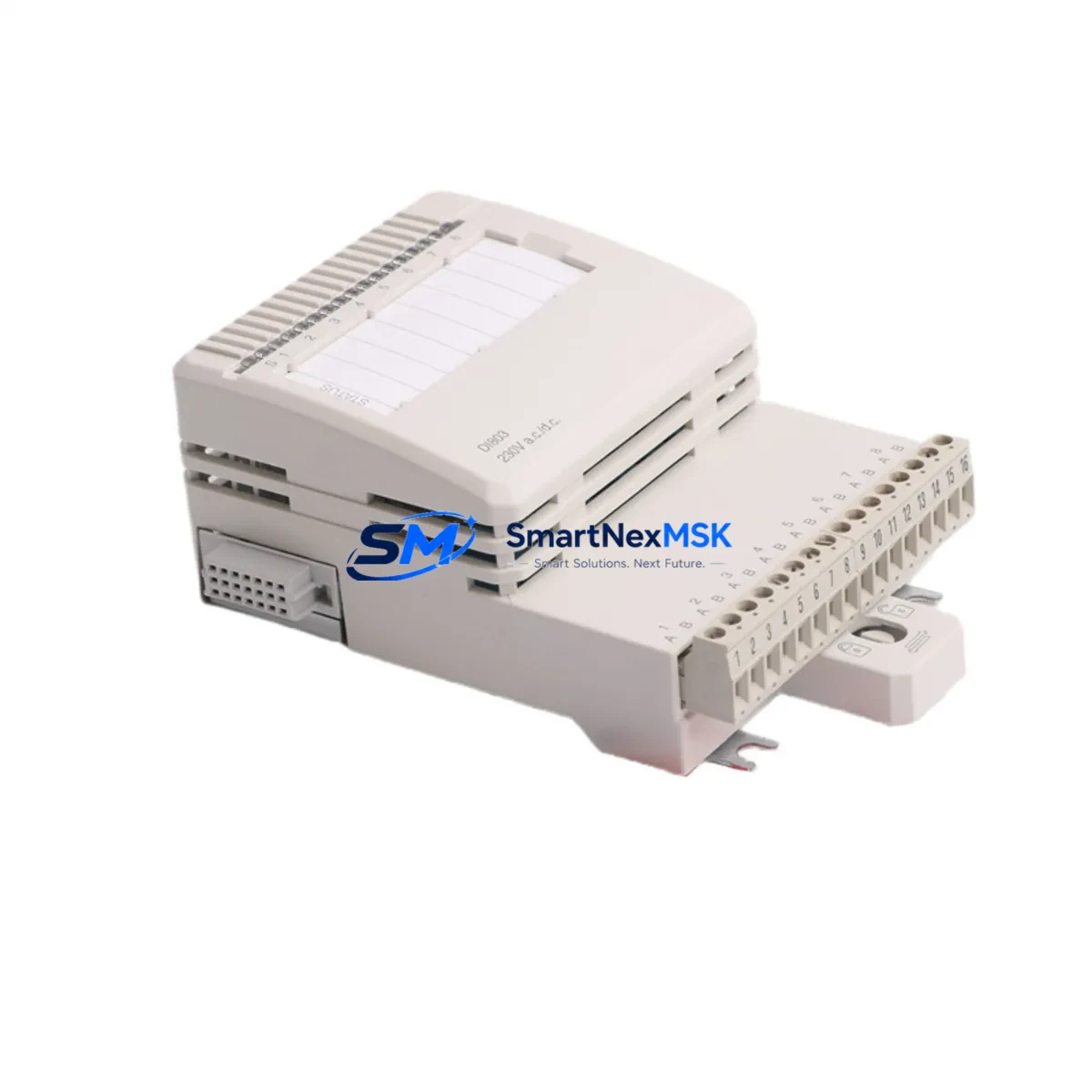
The ABB DI803 is an 8-channel, 230V AC digital input module engineered for the S800 I/O platform and fully compatible with the AC800M process controller family. As legacy DCS and PLC installations age, the DI803 has become one of the most sought-after retrofit components for engineers tasked with modernizing control cabinets without replacing the entire automation architecture. Whether you are sourcing a direct replacement for a failed unit, upgrading a discontinued spare, or planning a phased migration from an older I/O generation, the DI803 delivers the electrical and logical compatibility required for a low-risk, minimum-downtime changeover.
Each DI803 module slots directly into the S800 I/O backplane, sharing the same mechanical footprint and terminal block layout as its predecessors. This means field wiring — including 230V AC signal lines routed from field devices such as motor contactors, valve limit switches, and pressure switches — can be reconnected without modification. The module communicates over the S800 ModuleBus, ensuring seamless integration with the CI830, CI840, and CI854 communication interface modules already installed in your control cabinet. No firmware patching or address reassignment is required when replacing a like-for-like DI803 unit.
Upgrade Compatibility Table
| Parameter | DI803 Specification | Retrofit Notes |
|---|---|---|
| Input Channels | 8 × 230V AC | Direct replacement for DI810 (24V DC) requires field wiring review |
| Backplane Interface | S800 ModuleBus | Compatible with all S800 I/O stations; no adapter required |
| Controller Compatibility | AC800M (PM860, PM861, PM864, PM866) | Verified with Control Builder M; no library update needed |
| Communication Interface | CI830 / CI840 / CI854 (PROFIBUS / Ethernet) | Module address retained from original configuration |
| Terminal Block | TB820 / TB825 compatible | Existing field wiring reconnects without re-termination |
| Installation | DIN rail / S800 baseplate | Same mechanical footprint; no panel modification required |
| Replacement Recommendation | Direct drop-in for failed or EOL DI803 units | Confirm firmware version in AC800M project before swap |
| Commissioning Focus | Channel mapping, signal verification, force test | Use Control Builder M diagnostic view for live channel status |
| Warranty | 12-Month Warranty | Covers manufacturing defects; pre-shipment functional test included |
Retrofit Planning for Existing Automation Systems
A successful DI803 retrofit begins well before the module arrives on site. Engineers should start by auditing the existing S800 I/O station to confirm the number of occupied slots, the baseplate model (TB820 or TB825), and the current CI module type — whether CI830 for PROFIBUS DP or CI854 for IEC 61850 Ethernet. The AC800M controller’s Control Builder M project file should be backed up and the I/O list exported so that channel assignments for the DI803 can be cross-referenced against field device wiring schedules.
Power budget verification is a critical pre-installation step. The S800 I/O station draws module power from the PS800 power supply unit. Adding or replacing a DI803 should be evaluated against the total station load, particularly in dense cabinets where multiple DO810, AI810, AO810, and DI803 modules share a single PS800. If the power margin is tight, a second PS800 may be required before the retrofit proceeds.
For sites migrating from older S100 or S200 I/O generations to the S800 platform, the DI803 is frequently paired with a new CI840 communication interface and a PM864 controller module to form the backbone of the upgraded control node. In these scenarios, the HMI configuration in 800xA or Freelance must be updated to reflect the new I/O addresses, and operator graphics tied to the digital input signals — such as motor run/stop status and valve open/closed indicators — must be re-mapped accordingly.
Wiring adaptation is straightforward for like-for-like replacements. The 230V AC field signals connect to the TB820 terminal block, which clips onto the DI803 without tools. For sites using marshalling cabinets, the junction between the field cable and the module terminal should be inspected for insulation condition and terminal torque before energizing. A pre-commissioning insulation resistance test on the 230V AC signal circuits is recommended to rule out field wiring degradation that may have contributed to the original module failure.
Communication link integrity should be verified after module installation. On PROFIBUS DP networks using the CI830, the GSD file for the S800 I/O station must match the configured slave address. On Ethernet-based systems using the CI854, the IP address and subnet mask of the communication interface should be confirmed in the AC800M project before going online. A programming cable connection to the PM860 or PM864 controller allows the engineer to monitor the DI803 channel status in real time during the commissioning walk-through.
Downtime Control During System Migration
Minimizing production downtime during a DI803 replacement requires a structured hot-swap procedure. Where the process permits, the affected I/O station should be placed in a safe state — with outputs held at their last valid value using the AC800M’s redundancy or hold-last-value function — before the module is physically removed. This preserves control continuity for outputs driven by logic that reads the DI803 channels, preventing spurious trips or unexpected actuator movements during the swap interval.
The replacement DI803 should be pre-tested before installation. Our pre-shipment functional test verifies all 8 input channels against a 230V AC test source, confirms ModuleBus communication handshake, and checks the module’s internal diagnostics register. A test report is available on request. This eliminates the risk of installing a second faulty unit and extends the effective downtime window to the physical swap and signal verification steps only — typically 15 to 30 minutes for an experienced technician.
After installation, the AC800M controller will automatically detect the new DI803 on the ModuleBus and restore normal scan cycle operation. The engineer should verify each channel’s status in Control Builder M’s online diagnostic view, confirm that the HMI displays the correct field device states, and release the I/O station from hold mode. A final functional test — cycling each field device connected to the DI803 inputs and confirming the corresponding logic response in the controller — completes the commissioning record and supports the 12-month warranty claim process if required.
Retrofit Support FAQ
Q1: Is the DI803 a direct replacement for an existing failed DI803 unit in my S800 I/O station?
Yes. The DI803 is a direct drop-in replacement. It uses the same TB820 or TB825 terminal block, the same S800 ModuleBus backplane connector, and the same module address scheme. No changes to the AC800M project file are required for a like-for-like swap. Simply remove the failed module, insert the replacement, and verify channel status in Control Builder M.
Q2: What commissioning steps are required after installing the DI803?
After physical installation, connect to the AC800M controller via Control Builder M and confirm the DI803 appears online in the I/O station view. Verify all 8 channels report the correct field device states. Cycle each connected field device (e.g., motor contactor, valve limit switch) and confirm the corresponding input channel toggles correctly. Document the test results for your maintenance record and warranty file.
Q3: Can the DI803 be used with both PROFIBUS DP and Ethernet communication interfaces?
Yes. The DI803 communicates over the S800 ModuleBus regardless of the upstream communication interface. It is compatible with CI830 (PROFIBUS DP), CI840 (PROFIBUS DP with redundancy), and CI854 (IEC 61850 Ethernet). The choice of CI module is determined by your network topology, not by the DI803 itself.
Q4: What does the 12-month warranty cover, and how is a claim initiated?
The 12-month warranty covers manufacturing defects and functional failures under normal operating conditions. Each unit undergoes a pre-shipment functional test verifying all input channels and ModuleBus communication. To initiate a warranty claim, contact sales@smartnexmsk.com with your order number, a description of the fault, and the module’s serial number. Replacement or repair will be arranged within the warranty period at no additional cost.
© 2026 SMARTNEXMSK. All rights reserved.
Original Source: https://smartnexmsk.com
Contact: sales@smartnexmsk.com | +86 18259474341


