ABB DI830 3BSE013210R1 Maintenance-Ready Spare S800 Automation
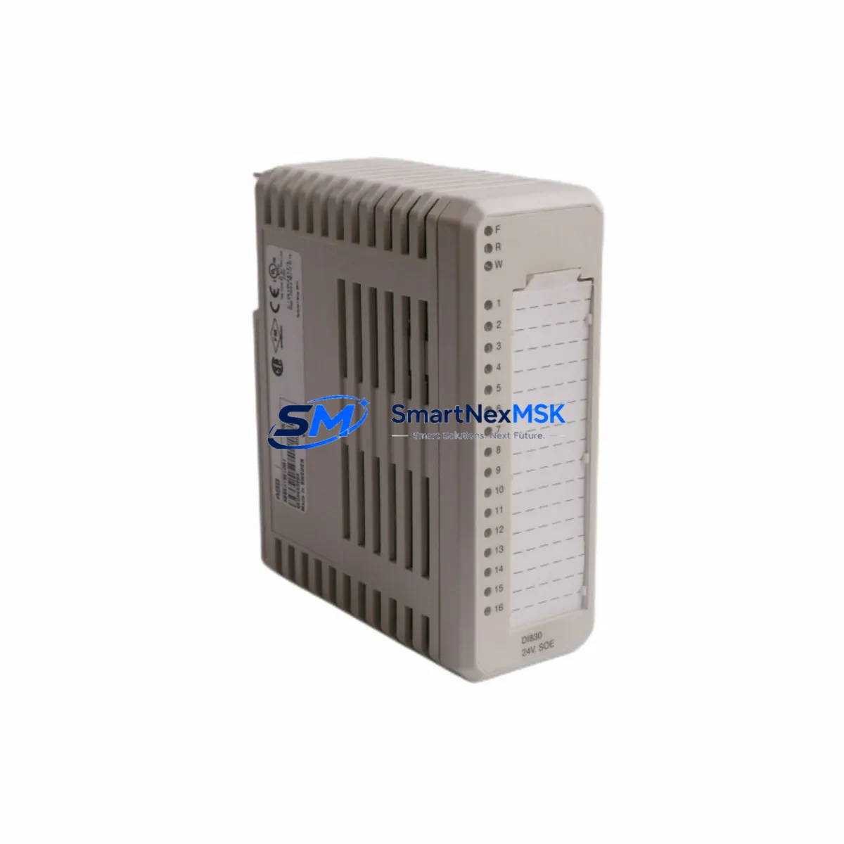
The ABB DI830 (3BSE013210R1) is a 16-channel, 24 VDC digital input module designed for the ABB S800 I/O system, fully compatible with AC800M distributed control system controllers. As a maintenance-ready original spare, the DI830 is a critical component in process automation environments where unplanned downtime carries significant operational and financial risk. Whether you are managing a planned shutdown, responding to a field fault, or building a strategic spare parts inventory, the DI830 3BSE013210R1 is a direct, plug-compatible replacement that restores system integrity without requiring controller reconfiguration or I/O mapping changes.
Sourced from verified supply channels and subjected to pre-shipment functional testing, each unit is dispatched with a 12-month warranty covering manufacturing defects and operational failures under normal industrial use conditions. Long-term supply continuity is supported for legacy AC800M installations where the original module may be discontinued or difficult to source through standard distribution.
Spare Maintenance Table
| Parameter | Specification |
|---|---|
| Part Number | DI830 / 3BSE013210R1 |
| Brand | ABB |
| Series | S800 I/O |
| Compatible Controller | AC800M (PM851, PM856, PM860, PM861, PM864, PM866) |
| Module Type | Digital Input Module |
| Number of Channels | 16 |
| Input Voltage | 24 VDC |
| Input Signal Type | Discrete / Digital (sourcing) |
| Communication Bus | S800 ModuleBus (via CI830 / CI840 / CI854 / CI858 interface) |
| Mounting | DIN rail via S800 I/O baseplate (TB820 / TB840) |
| Operating Temperature | 0 °C to +55 °C |
| Protection Class | IP20 |
| Origin | Germany |
| Condition | Original, pre-shipment tested |
| Warranty | 12 Months |
| Typical Application | Process DCS, Oil & Gas, Power, Pulp & Paper, Chemical |
| Maintenance Recommendation | Inspect baseplate connectors and field wiring terminals annually; verify LED status indicators during commissioning |
Maintenance Planning for Continuous Operation
When a DI830 3BSE013210R1 fault is detected — typically indicated by a red module fault LED or a diagnostic alarm in the AC800M controller — the replacement workflow should be treated as part of a broader control cabinet inspection rather than an isolated swap. Maintenance engineers should use the opportunity to audit the surrounding S800 I/O infrastructure for latent faults that could trigger the next unplanned outage.
Begin by verifying the 24 VDC field power supply feeding the I/O station. A degraded or undersized power supply — such as an aging SD831 or SD832 power distribution unit — can cause intermittent input read errors that mimic module failure. Confirm that supply voltage is within the 20.4–28.8 VDC operating range at the baseplate terminals under full load.
Next, inspect the TB820 or TB840 baseplate on which the DI830 is mounted. Corroded or mechanically stressed baseplate connectors are a common root cause of module communication faults in high-vibration or high-humidity environments. If the baseplate shows signs of discoloration, pin deformation, or contamination, replace it concurrently with the DI830 to avoid repeat failures.
The CI854 or CI858 PROFIBUS DP interface module — or the CI830 / CI840 ModuleBus coupler — connecting the S800 I/O station to the AC800M controller should also be checked. A failing communication interface can generate false module diagnostics across multiple I/O modules simultaneously. Verify that the interface module’s status LEDs indicate normal bus communication and that no CRC or timeout errors are logged in the controller’s event list.
Field wiring connected to the DI830’s 16 input channels should be inspected for insulation breakdown, loose terminal connections, and incorrect polarity. In installations using TB82 or TB84 terminal bases, confirm that all field cable shields are properly grounded and that no cross-wiring exists between adjacent channels. Where signal integrity is critical — particularly in long cable runs or electrically noisy environments — consider installing signal isolators or surge protection barriers upstream of the input channels to protect the replacement module.
If the DCS loop includes relay output modules such as the DO810 or DO820 controlling field devices whose feedback signals are read by the DI830, verify that the relay contacts are within specification and not causing false input states. Similarly, if the system uses analog input modules such as the AI830 or AI835 in adjacent slots, confirm that no ground loops or common-mode voltage issues are present that could affect digital input thresholds.
For installations where the DI830 is part of a redundant I/O configuration, ensure that the redundant module (if fitted) is also functional and that the switchover logic in the AC800M controller is operating correctly. Document the replacement in the site maintenance log and update the spare parts inventory to maintain the recommended minimum stock level of one DI830 per I/O station.
Site Replacement Workflow
Step 1 — Pre-replacement verification: Confirm the fault is isolated to the DI830 by reviewing the AC800M diagnostic log. Note the module slot address and I/O station identifier for post-replacement verification.
Step 2 — Safe isolation: Follow site lock-out/tag-out (LOTO) procedures. De-energize the field power supply to the affected I/O station. Do not remove the module under live field voltage.
Step 3 — Module removal: Release the DI830 from the TB820/TB840 baseplate by pressing the module release latch. Slide the module out of the baseplate slot. No tools are required for standard S800 module extraction.
Step 4 — Replacement installation: Insert the new DI830 3BSE013210R1 into the same baseplate slot. The module is keyed to prevent incorrect insertion. Confirm the module is fully seated and the latch is engaged.
Step 5 — Power restoration and commissioning: Re-energize the field power supply. The AC800M controller will automatically detect and configure the new module using the existing I/O configuration stored in the controller project. No manual address setting or DIP switch configuration is required for standard S800 hot-swap replacement.
Step 6 — Functional verification: Confirm all 16 input channels are reading correctly by exercising each field device and verifying the corresponding input state in the AC800M controller’s I/O diagnostic view. Clear any latched fault alarms in the DCS operator station.
Step 7 — Documentation: Record the replacement date, new module serial number, and post-replacement test results in the site maintenance management system (CMMS). Update the spare parts inventory and initiate a replenishment order to restore minimum stock levels.
Spare Parts Support FAQ
Q1: Is the DI830 3BSE013210R1 compatible with all AC800M controller versions?
The DI830 is compatible with all AC800M controller variants — including PM851, PM856, PM860, PM861, PM864, and PM866 — when used with a supported S800 I/O communication interface (CI830, CI840, CI854, or CI858). Compatibility is determined by the S800 ModuleBus architecture, not the specific controller firmware version. No hardware or software modification is required for direct replacement.
Q2: What pre-shipment testing is performed on each DI830 unit?
Each DI830 3BSE013210R1 is functionally tested prior to dispatch to verify channel integrity, module communication, and LED diagnostic behavior. Units that fail any test parameter are quarantined and not shipped. A test report is available upon request for critical infrastructure procurement.
Q3: How should the DI830 be stored as a long-term spare?
Store the DI830 in its original anti-static packaging in a dry, temperature-controlled environment (recommended: 0 °C to +40 °C, relative humidity below 75% non-condensing). Avoid storage near strong electromagnetic fields or corrosive atmospheres. Inspect stored units annually and rotate stock on a first-in, first-out basis to maintain readiness.
Q4: What is covered under the 12-month warranty?
The 12-month warranty covers manufacturing defects and operational failures under normal industrial operating conditions as specified in the ABB S800 I/O system documentation. Damage resulting from incorrect installation, overvoltage, reverse polarity, or physical impact is excluded. Warranty claims are processed with a replacement-first policy to minimize site downtime. Contact our technical support team with the module serial number and fault description to initiate a claim.
© 2026 SMARTNEXMSK. All rights reserved.
Original Source: https://smartnexmsk.com
Contact: sales@smartnexmsk.com | +86 18259474341


