ABB DO818 3BSE069053R1 Spare for S800 Automation: Spare Replacement & Industrial Downtime Risk Control
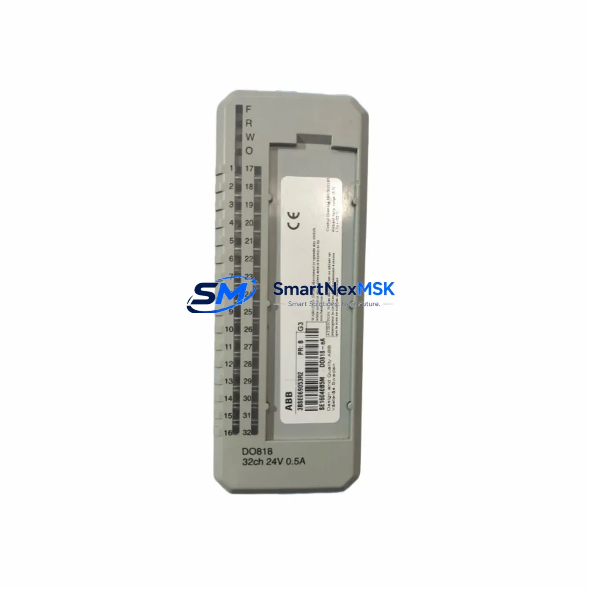
The ABB DO818 (3BSE069053R1) is an 8-channel 24VDC digital output module designed for the ABB AC800M controller platform and S800 I/O system. As a critical field-side output interface, the DO818 drives solenoid valves, motor starters, indicator lamps, and relay coils in continuous process environments including oil & gas, chemical, power generation, and pulp & paper plants. When this module fails or degrades, the downstream control loop is immediately compromised — making a verified, tested spare unit the single most effective tool for minimizing unplanned downtime.
Sourced from original ABB production, each DO818 3BSE069053R1 unit we supply is inspected, function-tested, and shipped with a 12-month warranty. Our inventory is maintained specifically to support maintenance engineers and procurement teams who cannot afford extended lead times on legacy DCS components.
Spare Maintenance Table
| Parameter | Specification |
|---|---|
| Part Number | DO818 / 3BSE069053R1 |
| Brand | ABB |
| Series | S800 I/O for AC800M |
| Module Type | Digital Output Module |
| Number of Channels | 8 channels |
| Output Voltage | 24 VDC |
| Output Current (per channel) | 0.5 A max |
| Total Load Current | 4 A max (all channels) |
| Output Type | Transistor (sourcing) |
| Short-Circuit Protection | Yes, electronic |
| Isolation | Optocoupler isolated, channel-to-bus |
| Backplane Interface | S800 ModuleBus |
| Compatible Controller | ABB AC800M (PM860, PM861, PM864, PM866) |
| Compatible I/O Station | TB820V2, TB840A, TB845 |
| Operating Temperature | 0°C to +55°C |
| Humidity | 5–95% RH, non-condensing |
| Mounting | DIN rail via S800 I/O base unit |
| Origin | Germany |
| Warranty | 12 months from shipment date |
| Condition | Original, function-tested before dispatch |
| Shipping | Worldwide, ESD-safe packaging |
Maintenance Planning for Continuous Operation
Replacing the DO818 3BSE069053R1 in the field is rarely an isolated task. A disciplined maintenance engineer will treat this module swap as an opportunity to audit the entire I/O station and associated control cabinet. Before declaring the loop restored, the following components should be inspected or tested alongside the DO818 replacement:
Power Supply Integrity: The S800 I/O station is powered through the TB820V2 or TB840A termination unit. Verify that the 24VDC field power supply — typically an ABB CP-E 24/10.0 or equivalent — is within tolerance and free of ripple. A marginal power supply is a common root cause of intermittent digital output faults that are misdiagnosed as module failure.
Termination Unit and Wiring: The DO818 plugs into a dedicated base unit (TB820V2 series). Inspect the base unit connector pins for corrosion, bent contacts, or mechanical wear. Check field wiring terminals for loose connections, especially on high-cycle outputs driving solenoid valves. Loose terminals cause voltage drop that can prevent output loads from energizing reliably.
Adjacent I/O Modules: In a shared S800 I/O station, a failed DO818 can sometimes indicate bus communication stress. Inspect neighboring modules such as the DI810 or DI811 digital input modules and the AO810V2 analog output module for fault LEDs or diagnostic alarms in the AC800M controller. A single corrupted ModuleBus frame can affect multiple modules simultaneously.
Communication and Controller Health: Confirm that the AC800M processor module (PM864 or PM866) is not logging ModuleBus timeout errors. If the controller has been running without a scheduled firmware update, this is an appropriate time to verify compatibility between the controller firmware version and the S800 I/O module library. The CI854 or CI858 PROFIBUS communication interface modules should also be checked for active fault codes if the station is connected to a PROFIBUS DP network.
Relay and Load-Side Verification: Many DO818 output channels drive intermediate relay modules — such as the ABB CR-M series or Phoenix Contact PLC-RSC relay couplers — before reaching the final load. After replacing the DO818, verify that each relay coil is energizing correctly and that the relay contacts are not welded or worn. A failed relay downstream of a healthy output module will produce identical symptoms to a failed DO818 from the operator’s perspective.
Signal Isolation and Protection: For outputs connected to inductive loads (solenoids, motor contactors), confirm that flyback suppression diodes or varistors are installed at the load terminals. Missing or failed suppression components generate voltage spikes that degrade output transistors over time and can cause premature DO818 failure. Signal isolators such as the MTL5500 series or Phoenix Contact MINI Analog isolators used in mixed-signal cabinets should also be checked for drift.
Fusing and Cabinet Protection: Review the fuse ratings on the 24VDC field power distribution rail. Undersized fuses that have been replaced with higher-rated substitutes are a common field modification that removes overcurrent protection from the DO818 output channels. Restore correct fuse ratings as part of the maintenance record.
Maintaining a minimum stock of one DO818 3BSE069053R1 per AC800M I/O station — alongside one DI810 digital input module and one AO810V2 analog output module — is a widely adopted spare parts strategy for plants running ABB S800-based DCS systems. This three-module buffer covers the most common field-replaceable unit failures without requiring an emergency procurement cycle.
Site Replacement Workflow
Step 1 — Confirm Compatibility: Verify that the installed base unit is a TB820V2 or TB840A. The DO818 3BSE069053R1 is not compatible with older TB810 or TB811 base units without an adapter. Check the AC800M project configuration in Control Builder M to confirm the module address and channel assignment before removal.
Step 2 — Safe Isolation: Place the affected I/O station in forced manual mode from the DCS operator station. De-energize the 24VDC field power supply to the station. Do not rely solely on software inhibit — physically isolate field power before handling the module to protect both personnel and connected field devices.
Step 3 — Module Removal: Press the module release latch and slide the DO818 out of the base unit. Note the LED status at the moment of removal if the module was still powered — a solid red LED indicates a hardware fault, while a flashing red LED typically indicates a configuration mismatch or communication loss.
Step 4 — Spare Installation: Insert the replacement DO818 3BSE069053R1 into the base unit until the latch clicks. Restore 24VDC field power. The AC800M controller will automatically detect the new module and download the channel configuration within seconds — no manual re-parameterization is required for a like-for-like replacement.
Step 5 — Functional Verification: From the DCS operator station, force each of the 8 output channels ON and OFF individually and confirm correct field device response. Check the module diagnostic page in Control Builder M for any residual fault codes. Return the I/O station to automatic control only after all 8 channels have been verified.
Step 6 — Documentation: Record the replacement in the plant maintenance management system (CMMS) with the old module serial number, new module serial number, date, and technician ID. Update the spare parts inventory to trigger a replenishment order for the consumed DO818 unit.
Spare Parts Support FAQ
Q: Is the DO818 3BSE069053R1 still available as a new original part, or is it discontinued?
A: The DO818 3BSE069053R1 remains available through authorized spare parts channels. ABB has not issued an end-of-life notice for this module as of the current date. We maintain stock specifically to support plants that cannot transition to newer I/O platforms on short notice. All units we supply are original ABB production, not refurbished or third-party compatible substitutes.
Q: What testing is performed before shipment?
A: Each DO818 unit undergoes a functional output test on a live S800 I/O station before packaging. We verify that all 8 channels switch correctly, that the ModuleBus communication link is established, and that no fault LEDs are active. The module is then packed in ESD-safe anti-static bags with foam cushioning for transit protection. A test report is available on request.
Q: Can the DO818 replace an older DO810 or DO814 module in an existing S800 station?
A: The DO818 uses the same S800 ModuleBus interface and is physically compatible with the same base units as the DO810 and DO814. However, the channel count and output current ratings differ between models. A Control Builder M configuration update is required to change the module type in the project. We recommend confirming the base unit type and controller firmware version before ordering a cross-model replacement. Our technical team can assist with compatibility verification prior to purchase.
Q: What does the 12-month warranty cover, and what is the return process?
A: The 12-month warranty covers hardware defects and functional failures under normal operating conditions. It does not cover damage caused by incorrect installation, overvoltage events, or physical impact. If a warranty claim is required, contact us with the order number and a description of the fault. We will arrange return shipping and provide a replacement unit or full refund within 5 business days of receiving the returned module. Warranty period begins from the shipment date shown on the invoice.
© 2026 SMARTNEXMSK. All rights reserved.
Original Source: https://smartnexmsk.com
Contact: sales@smartnexmsk.com | +86 18259474341


