ABB DO820 3BSE008514R1 Retrofit-Ready Relay Output for S800 Control Systems
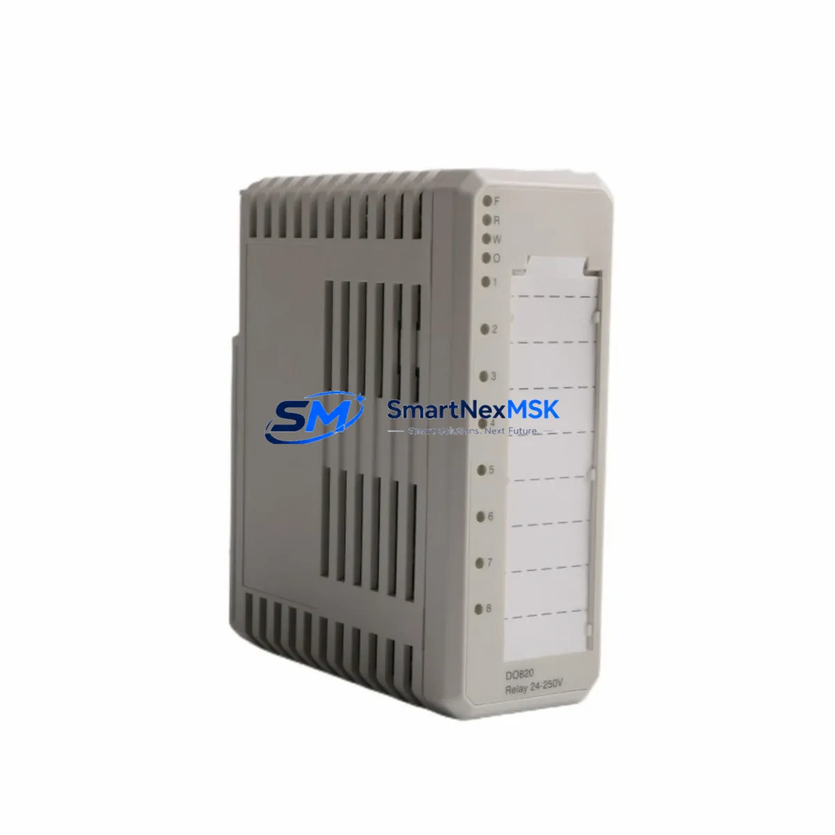
The ABB DO820 (3BSE008514R1) is a 16-channel relay digital output module engineered for the S800 I/O distributed I/O platform, widely deployed alongside AC800M process controllers in power generation, pulp and paper, oil and gas, and chemical processing facilities. As legacy DCS and PLC installations approach end-of-life, the DO820 has become one of the most sought-after retrofit components for engineers tasked with modernizing control cabinets without full system replacement.
Whether you are replacing a failed module in an aging control loop, upgrading a discontinued spare, or executing a phased migration from an older Advant OCS or MOD 300 platform to the current AC800M architecture, the DO820 3BSE008514R1 provides a direct, rack-compatible solution that preserves existing wiring, terminal assignments, and program logic with minimal re-engineering effort.
Upgrade Compatibility Table
| Parameter | Details |
|---|---|
| Module Model | ABB DO820 / 3BSE008514R1 |
| Output Channels | 16 × Relay (SPDT) |
| Compatible Rack / Backplane | S800 I/O Baseunit (TB820, TB825, TB840) |
| Compatible Controller | AC800M (PM860, PM861, PM864, PM866) |
| Communication Interface | ModuleBus (via S800 I/O Station) |
| Replaces / Upgrades From | DO810, DO815, DO818 (channel count or relay type differences — verify load requirements) |
| Installation Requirement | Snap-fit onto S800 Baseunit; no tools required for module swap |
| Address Configuration | Module address set via TB820/TB825 DIP switch or software node assignment in Control Builder M |
| Program Compatibility | IEC 61131-3 function blocks in Control Builder M; existing DO channel tags remain valid on direct replacement |
| HMI / SCADA Impact | No graphic changes required on direct replacement; verify tag mapping if baseunit type changes |
| Communication Link Check | Confirm MMS / OPC DA / OPC UA server tag refresh after hot-swap or cold-swap |
| Debugging Focus | Relay contact continuity test, output forcing in Control Builder M, field device response verification |
| Warranty | 12 Months — covers manufacturing defects and functional failure under normal operating conditions |
Retrofit Planning for Existing Automation Systems
A successful DO820 retrofit begins well before the module arrives on site. Engineers should first audit the existing TB820 or TB825 baseunit to confirm the slot position, verify that the backplane bus is free of corrosion or mechanical damage, and document the current DIP switch address settings. In multi-station configurations where several S800 I/O stations are daisy-chained via PROFIBUS DP or the internal ModuleBus, it is critical to record the station node address before powering down to avoid address conflicts during recommissioning.
Power budget validation is a frequently overlooked step. The DO820 draws its logic power from the SD821 or SD822 power supply module mounted in the same cabinet section. Before inserting the replacement module, confirm that the available current margin on the 24 VDC rail is sufficient, particularly in cabinets where additional AI810, AO810, or DI810 analog and digital input modules share the same power feed. Overloaded rails are a common root cause of intermittent module faults in aging installations.
Terminal wiring on the DO820 is handled through the baseunit’s field terminal block, meaning the module itself can be swapped without disturbing field cables — a significant advantage during live-plant maintenance windows. However, engineers should inspect the TB820 terminal block for loose connections, oxidized contacts, or undersized wire ferrules before reinserting the new module. Relay output loads should be re-verified against the DO820’s rated contact capacity (250 VAC / 5 A resistive) to ensure compatibility with connected actuators, solenoid valves, and motor starters.
For sites migrating from older Advant Controller 450 or Master fieldbus architectures, the DO820 retrofit typically involves installing a new CI854 PROFIBUS DP communication interface or CI858 DNP3 interface to bridge legacy field devices to the AC800M controller. In these scenarios, the Control Builder M project must be updated to include the new hardware tree, and all DO channel function blocks must be re-linked to the new physical addresses. A full offline simulation in Control Builder M prior to site work is strongly recommended.
HMI screens built on ABB 800xA or third-party SCADA platforms referencing DO820 output tags will generally require no modification on a like-for-like module swap. However, if the baseunit type changes (e.g., from TB820 to TB840A for redundancy), tag path updates in the 800xA Aspect Directory may be necessary. Coordinate with the DCS engineer responsible for the graphics library before finalizing the retrofit scope.
Programming cable access is required if the AC800M controller needs a firmware update or if the Control Builder M project must be downloaded after hardware changes. Ensure a TK212A USB programming cable or Ethernet connection to the controller’s service port is available on site. Backup the existing controller project to a secure location before any download operation.
Downtime Control During System Migration
Minimizing unplanned downtime is the primary concern for any DO820 replacement in a running production environment. The S800 I/O platform supports hot-swap module replacement when the baseunit is configured for non-redundant operation and the connected process permits a brief output interruption. Before initiating a hot-swap, place all affected output channels in a safe state using the force function in Control Builder M or by issuing a controlled shutdown command to the connected field devices.
For processes where even momentary output loss is unacceptable — such as burner management systems or safety-instrumented loops — plan the swap during a scheduled maintenance window and implement a manual bypass on the affected output circuits. Document the bypass procedure in the site’s management of change (MOC) system and obtain the required permits before work begins.
After inserting the DO820, the AC800M controller will automatically detect the new module via the ModuleBus scan and restore output states based on the last known program values, provided the controller has not been restarted. Verify each output channel individually using the diagnostic display in Control Builder M and confirm field device response before releasing the process back to automatic control. Log the replacement in the site’s maintenance management system with the new module serial number and the date of installation to support future warranty claims and spare parts planning.
Maintaining a minimum of one DO820 3BSE008514R1 as a cold-standby spare in the site’s instrument store is strongly recommended for facilities with multiple S800 I/O stations. Given the global supply constraints on legacy ABB S800 components, securing stock in advance significantly reduces the risk of extended unplanned outages.
Retrofit Support FAQ
Q1: Is the DO820 3BSE008514R1 a direct drop-in replacement for the DO810 or DO815?
The DO820 shares the same S800 baseunit form factor and ModuleBus interface as the DO810 and DO815, but differs in channel count and relay contact configuration. The DO820 provides 16 relay outputs versus 8 on the DO810. Verify that your Control Builder M hardware configuration reflects the correct module type and that the field wiring load does not exceed the DO820’s relay contact ratings before completing the swap.
Q2: Can the DO820 be commissioned without taking the AC800M controller offline?
In most non-redundant S800 configurations, the DO820 supports hot-swap insertion. The controller will re-scan the ModuleBus and recognize the new module automatically. However, output channels will be in a de-energized state during the scan cycle. Always place connected field devices in a safe state before insertion and verify all outputs after the module is recognized by the controller.
Q3: What wiring checks are required before inserting the replacement DO820?
Inspect the TB820 or TB825 baseunit terminal block for loose wire ferrules, oxidized contacts, and correct wire gauge. Confirm that the 24 VDC supply rail from the SD821 or SD822 power module is within tolerance (18–30 VDC). Measure relay load voltage and current at each output terminal to ensure compatibility with the DO820’s rated contact capacity. Document all findings before module insertion.
Q4: What does the 12-month warranty cover, and how is a warranty claim initiated?
The 12-month warranty covers manufacturing defects and functional failures under normal operating conditions from the date of shipment. It does not cover damage resulting from incorrect installation, overvoltage, or unauthorized modification. To initiate a warranty claim, contact sales@smartnexmsk.com with the module serial number, purchase order reference, and a description of the fault. A replacement or repair will be arranged within the warranty period.
© 2026 SMARTNEXMSK. All rights reserved.
Original Source: https://smartnexmsk.com
Contact: sales@smartnexmsk.com | +86 18259474341


