ABB DPW03 Retrofit-Ready Power Supply for DPW Series Control Systems
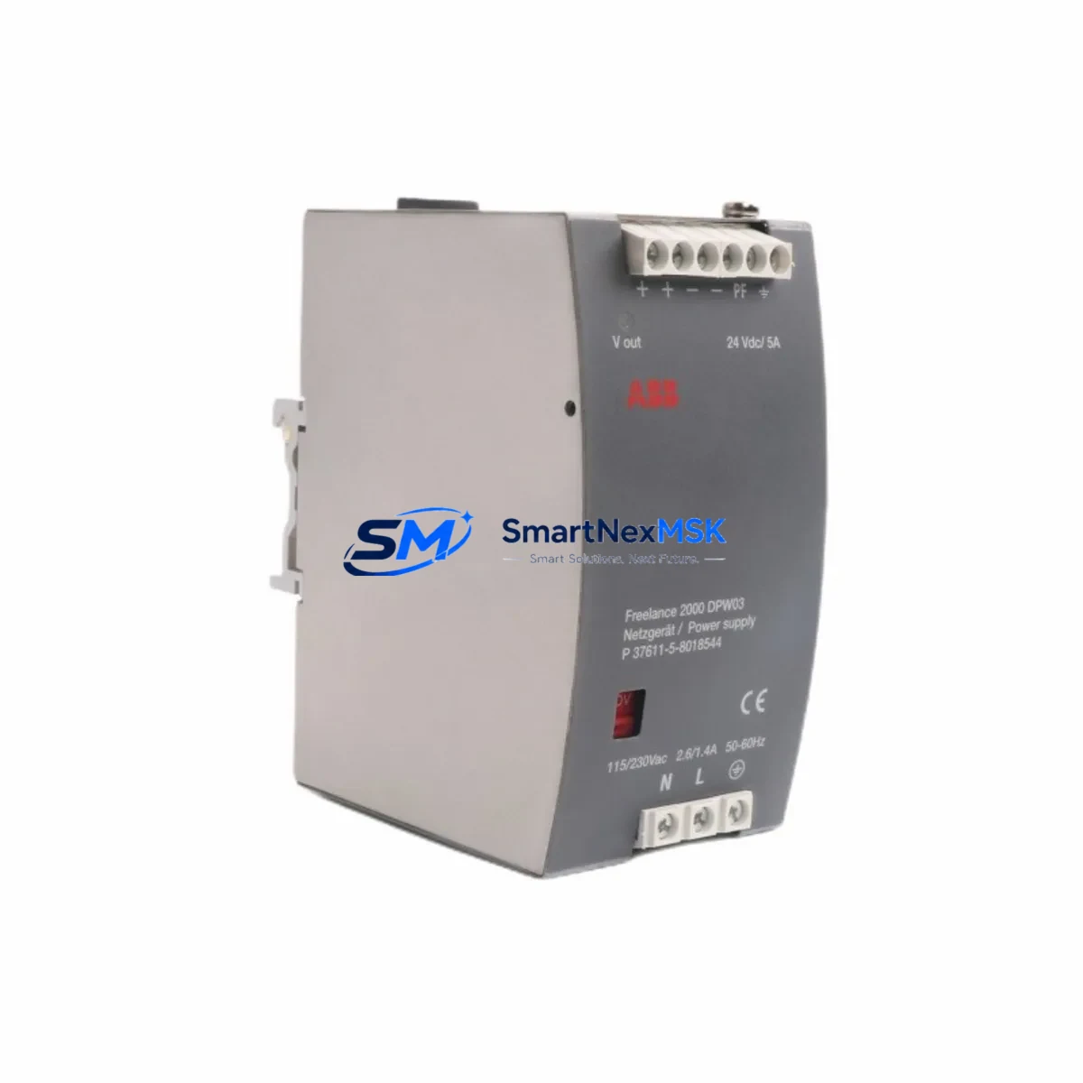
The ABB DPW03 (part numbers P37611-5-8018644 / 8018544M) is a proven retrofit-ready power supply module engineered for seamless integration into legacy DPW Series distributed control and automation systems. As original DPW Series hardware reaches end-of-life and spare parts become increasingly scarce, the DPW03 serves as the authoritative drop-in replacement for aging or failed power supply units — enabling plant engineers and system integrators to restore full control system functionality with minimal disruption to ongoing production.
Whether you are managing a scheduled control cabinet upgrade, responding to an unplanned power supply failure, or executing a phased migration from an obsolete automation platform, the DPW03 delivers the electrical compatibility, mechanical form factor, and firmware alignment required to maintain continuity across your existing ABB control architecture. This module is fully compatible with the DPW Series backplane and rack infrastructure, and it interfaces directly with associated I/O modules, communication modules, and controller units already installed in your cabinet.
Upgrade Compatibility Table
| Parameter | Details |
|---|---|
| Replacement Target | ABB DPW03 / P37611-5-8018644 / 8018544M |
| Compatible Series | ABB DPW Series Distributed Control Systems |
| Module Type | Power Supply Module |
| Backplane Interface | DPW Series standard backplane connector — direct slot replacement |
| Mounting | DIN rail / rack-mount per original DPW Series cabinet specification |
| Communication Compatibility | Compatible with PROFIBUS, PROFINET, and proprietary ABB DPW bus protocols as configured in the original system |
| I/O Module Compatibility | Supports existing DI, DO, AI, AO modules installed on the same rack |
| Replacement Recommendation | Direct swap; verify terminal wiring map and power rail voltage before installation |
| Commissioning Notes | Confirm module address assignment, re-validate HMI tag mapping, and perform loop check on all connected I/O channels post-installation |
| Warranty | 12-Month Warranty — covers manufacturing defects and functional failure under normal operating conditions |
Retrofit Planning for Existing Automation Systems
Successful retrofit of the DPW03 into an operational control system requires careful pre-installation planning. Before removing the failed or aging power supply, engineers should document the existing terminal wiring layout, confirm the input voltage range (typically 24 VDC or 120/230 VAC depending on cabinet configuration), and verify that the replacement module’s output current capacity meets the aggregate load of all downstream modules on the same power rail.
In a typical DPW Series control cabinet, the power supply module feeds a shared backplane that supports a combination of digital input modules, digital output modules, analog input modules, and analog output modules. The DPW03 is designed to sustain these loads within the original power budget. If the retrofit is part of a broader system expansion — for example, adding additional I/O capacity through supplementary racks or extending the control network — engineers should recalculate total power consumption before finalizing the replacement specification.
Communication continuity is a critical concern during any power supply retrofit. In systems where the DPW Series controller communicates via PROFIBUS DP or PROFINET IO, the network segment must remain stable during the module swap. Where possible, plan the replacement during a scheduled maintenance window and coordinate with the SCADA or DCS operator to place the affected controller in a safe hold state. If the system uses an ABB AC500 series CPU or an ABB Freelance DCS controller as the upstream master, ensure that the watchdog timeout parameters are configured to tolerate the brief interruption during module hot-swap or cold-swap procedures.
Terminal block wiring should be photographed and mapped prior to disconnection. Many DPW Series installations use Phoenix Contact or Weidmüller terminal blocks for field wiring termination, and the wiring sequence must be preserved exactly to avoid I/O channel misassignment after reinstallation. If the cabinet also contains an ABB CP600 or CP620 HMI panel, verify that the HMI tag database references the correct module slot address after the replacement is complete — slot address conflicts are a common source of post-retrofit commissioning delays.
For systems that include communication gateways or protocol converters — such as units bridging legacy Modbus RTU field devices to a PROFIBUS backbone — confirm that the gateway’s power supply input is not sourced from the same rail as the DPW03 output. Isolating the gateway power feed prevents cascading failures during the replacement procedure and protects the integrity of the communication link to field instruments.
Downtime Control During System Migration
Minimizing unplanned downtime is the primary operational objective when replacing a power supply module in a live automation environment. The DPW03 retrofit process is designed to support a structured, low-risk replacement workflow that protects existing program logic, preserves field wiring integrity, and maintains control system continuity throughout the migration.
Prior to initiating the physical swap, export and archive the current PLC or DCS program from the controller — whether that is an ABB AC500 PM573, PM583, or PM595 CPU, or a Freelance DCS controller node. Store the program backup on an isolated engineering workstation and verify the backup file integrity before proceeding. This step ensures that if any unexpected configuration loss occurs during the power cycle, the original control logic can be restored within minutes rather than hours.
During the replacement window, place all affected output modules in a safe de-energized state and notify field operators of the temporary suspension of automatic control. For continuous process applications — such as conveyor drives, pump control panels, or temperature regulation loops — coordinate with the process team to switch to manual override or local control mode at the field device level. This prevents process upsets caused by the momentary loss of controller output signals during the power supply changeover.
After installing the DPW03 and restoring power to the backplane, perform a systematic channel-by-channel I/O verification before returning the system to automatic mode. Confirm that all digital input status indicators match the known field device states, verify analog input readings against independent field measurements, and test each digital output channel by commanding a known state from the engineering workstation. Only after all channels are verified should the controller be returned to automatic program execution.
All units supplied by SMARTNEXMSK are pre-tested prior to shipment and covered by a 12-month warranty against manufacturing defects and functional failure. In-stock inventory is maintained to support urgent replacement requirements, with same-day dispatch available for orders confirmed before the daily shipping cutoff.
Retrofit Support FAQ
Q1: Is the ABB DPW03 a direct replacement for the original DPW Series power supply without hardware modification?
Yes. The DPW03 is designed as a form-fit-function replacement for the original DPW Series power supply slot. No hardware modification to the backplane, rack, or cabinet wiring is required, provided the input voltage specification of the replacement module matches the original installation. Always verify the input voltage range and output current rating against your existing system documentation before installation.
Q2: What commissioning steps are required after installing the DPW03?
After physical installation and power restoration, the recommended commissioning sequence includes: (1) confirm module address assignment in the controller configuration matches the original slot assignment; (2) verify all I/O module status LEDs indicate normal operation; (3) perform a full I/O loop check on all connected digital and analog channels; (4) validate HMI tag mapping if an ABB CP600, CP620, or equivalent panel is connected; and (5) confirm communication link integrity to any upstream SCADA, DCS, or PROFIBUS master before returning to automatic control mode.
Q3: Can the DPW03 be used in systems that have been partially upgraded to newer ABB hardware?
Yes. The DPW03 is compatible with mixed-generation DPW Series installations where some modules have been upgraded while others remain on original hardware. It is also compatible with systems where the communication backbone has been migrated from legacy proprietary protocols to PROFIBUS DP or PROFINET IO, provided the power supply slot specification has not changed. Consult your system’s hardware configuration documentation to confirm backplane compatibility before ordering.
Q4: What does the 12-month warranty cover, and what is the return process?
The 12-month warranty covers manufacturing defects and functional failure under normal operating conditions from the date of shipment. It does not cover damage resulting from incorrect installation, overvoltage events, or physical mishandling. To initiate a warranty claim, contact SMARTNEXMSK with the original order reference and a description of the observed fault. Replacement or repair will be arranged promptly to minimize impact on your production schedule.
© 2026 SMARTNEXMSK. All rights reserved.
Original Source: https://smartnexmsk.com
Contact: sales@smartnexmsk.com | +86 18259474341


