ABB DSBB170A 57310256-EB Retrofit-Ready Bus Backplane for ADVANT MOD 300 Control Systems
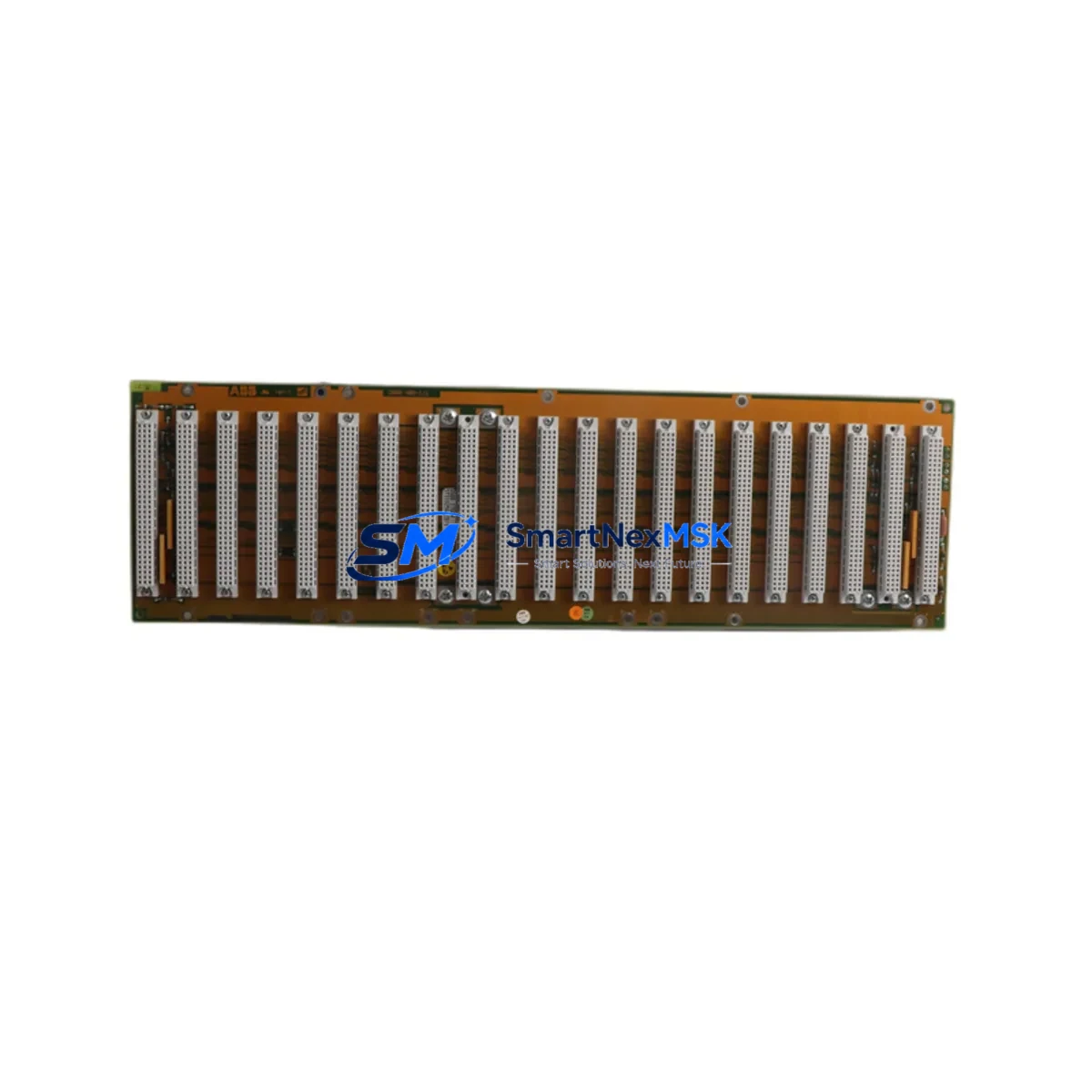
The ABB DSBB170A (Part No. 57310256-EB) is a bus backplane board engineered for the ADVANT MOD 300 distributed control system platform. As legacy ADVANT installations approach end-of-life and spare parts become increasingly scarce, this module serves as a direct, drop-in retrofit solution for system integrators, plant engineers, and maintenance teams managing aging control infrastructure. Whether you are replacing a failed backplane in a running production line or executing a planned control cabinet upgrade, the DSBB170A delivers the electrical and mechanical compatibility required to restore system integrity with minimal disruption.
The ADVANT MOD 300 architecture relies on a modular rack-and-backplane topology where the backplane provides the communication backbone between processor modules, I/O modules, and communication interfaces. The DSBB170A supports this topology by maintaining the internal bus structure that allows modules such as the DSPC172 processor board, DSAI130 analog input modules, and DSDO115 digital output modules to exchange data with the system controller. When a backplane fails or degrades, the entire rack segment becomes non-functional — making rapid, verified replacement stock a critical operational requirement.
Upgrade Compatibility Table
| Parameter | Details |
|---|---|
| SKU / Part Number | DSBB170A / 57310256-EB |
| Compatible Platform | ABB ADVANT MOD 300 DCS |
| Module Function | Bus Backplane Board (rack communication backbone) |
| Replaces / Supersedes | DSBB170, DSBB110A (earlier backplane revisions) |
| Rack / Chassis Fit | Standard ADVANT MOD 300 subrack; verify slot count before ordering |
| Bus Interface | ADVANT internal S-bus; compatible with DSPC172, DSAI130, DSDO115, DSDI110A |
| Communication Compatibility | MasterBus 300, PROFIBUS DP (via DSCS021 coupler), Modbus RTU |
| Power Supply Requirement | 24 VDC rack power; confirm DSPU110 or DSPU130 power unit capacity |
| Installation Requirement | De-energize rack; reseat all module connectors after backplane swap |
| Firmware / Software | No firmware on backplane; host controller retains existing program logic |
| Retrofit Recommendation | Replace backplane during planned shutdown; perform full I/O scan post-installation |
| Commissioning Focus | Verify module addressing, re-establish MasterBus 300 link, confirm HMI tag mapping |
| Warranty | 12 Months — covers manufacturing defects and functional failure under normal operating conditions |
Retrofit Planning for Existing Automation Systems
Successful backplane replacement in an ADVANT MOD 300 system requires careful pre-work across several subsystems. Before removing the failed DSBB170A, engineers should document the physical slot assignments of all installed modules — including the DSPC172 processor, any DSAI130 or DSAI145 analog input cards, DSDO115 digital output modules, and the DSDI110A digital input boards. Slot position directly affects module addressing in the ADVANT controller configuration, and any deviation from the original layout will require corresponding changes in the engineering workstation software.
Power budget verification is equally critical. The DSPU110 or DSPU130 rack power supply must have sufficient headroom to support all modules reinstalled on the new backplane. Overloaded power supplies are a common root cause of intermittent faults following backplane replacement and should be load-tested before the system is returned to service.
Communication link restoration is the next priority. ADVANT MOD 300 systems typically use MasterBus 300 as the primary inter-rack communication protocol. After backplane installation, the MasterBus 300 link must be re-established and verified at the controller level. Where PROFIBUS DP is used for field device communication — routed through a DSCS021 PROFIBUS coupler — the coupler’s GSD configuration and slave address assignments must be confirmed intact. Systems using Modbus RTU for legacy instrument integration should verify baud rate, parity, and station address settings have not been disrupted during the hardware swap.
For sites running Operator Station OS 300 or third-party SCADA/HMI platforms connected to the ADVANT system, HMI tag mapping should be validated after the backplane is energized. Tag loss or address shift errors are most commonly detected at this stage. Having a pre-swap export of the tag database and a reference screenshot of key HMI faceplates significantly reduces troubleshooting time. If the site uses a DSMB170 MasterBus interface module or a DSBC172 bus coupler for inter-rack expansion, these should also be reseated and their link status confirmed before declaring the system ready for production.
Finally, a full I/O scan and loop check — covering at minimum the critical control loops served by the affected rack — should be completed before handover. This includes verifying analog signal scaling on DSAI130 channels, confirming digital output states on DSDO115 cards, and checking that the controller’s cyclic task execution time has not increased beyond acceptable limits following the hardware change.
Downtime Control During System Migration
Minimizing unplanned downtime during a backplane replacement is achievable with disciplined pre-staging and a structured cutover sequence. The most effective approach is to pre-configure and bench-test the replacement DSBB170A before the maintenance window opens. This means physically inspecting the new backplane for connector integrity, confirming part number and revision match, and — where possible — performing a powered bench test with a spare DSPC172 processor to verify bus continuity.
During the cutover window, the recommended sequence is: (1) export and archive the current controller program from the engineering workstation; (2) de-energize the rack via the DSPU110/DSPU130 power supply; (3) photograph and label all module positions before extraction; (4) swap the backplane; (5) reinstall modules in their original slot positions; (6) re-energize and monitor the MasterBus 300 link status; (7) perform a controlled program download if required; (8) execute the I/O scan and loop check. This sequence, when followed precisely, typically allows a single-rack backplane replacement to be completed within a two-to-four hour maintenance window, preserving the original program logic and minimizing the risk of configuration drift.
For systems where a cold standby rack is available, the preferred strategy is to pre-build the standby rack with the new DSBB170A and all required modules, then perform a hot-swap at the rack level rather than a module-level backplane replacement. This approach reduces the active cutover window to under 30 minutes and eliminates the risk of module reseating errors under time pressure.
Retrofit Support FAQ
Q1: Is the DSBB170A a direct drop-in replacement for the DSBB170 and DSBB110A?
The DSBB170A is the current production revision and is mechanically and electrically compatible with the DSBB170 and DSBB110A in standard ADVANT MOD 300 subracks. Verify the subrack slot count and connector row configuration before installation, as early-generation subracks may have minor mechanical differences. No software changes are required on the host controller when replacing like-for-like.
Q2: Will my existing controller program and HMI configuration remain intact after the backplane swap?
Yes. The DSBB170A is a passive bus backplane and does not store program logic or configuration data. All program logic resides in the DSPC172 processor module and the engineering workstation project archive. Provided modules are reinstalled in their original slot positions and the MasterBus 300 link is re-established correctly, the controller will resume execution of the existing program without requiring a full download. HMI tag mapping should be validated post-swap as a standard commissioning step.
Q3: What pre-shipment testing is performed on the DSBB170A?
Each DSBB170A unit undergoes functional verification prior to dispatch, including bus continuity testing and connector integrity inspection. Units are shipped in anti-static packaging with individual test records. The 12-month warranty covers manufacturing defects and functional failure under normal operating conditions and begins from the date of delivery.
Q4: What information should I provide when ordering to ensure compatibility?
Please confirm: (1) the full part number including revision suffix (57310256-EB); (2) the subrack model and slot count in your installation; (3) the firmware revision of your DSPC172 processor if known; and (4) the communication protocols in use (MasterBus 300, PROFIBUS DP, Modbus RTU). Our technical team will cross-reference your configuration against available stock and confirm compatibility before shipment.
© 2026 SMARTNEXMSK. All rights reserved.
Original Source: https://smartnexmsk.com
Contact: sales@smartnexmsk.com | +86 18259474341


