ABB DSQC351A Retrofit-Ready Power Supply for IRC5 Control Systems
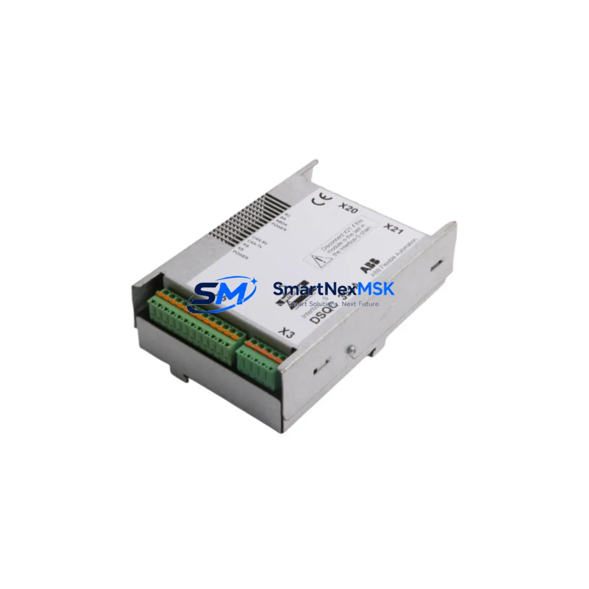
The ABB DSQC351A is a proven power supply module engineered for the IRC5 robot controller platform, widely deployed across automotive, metal fabrication, and general industrial automation lines. As ABB continues to evolve its robotics portfolio, many facilities operating legacy IRC5 cabinets face the challenge of sourcing reliable replacement components for aging or discontinued hardware. The DSQC351A addresses this need directly — offering a compatible, retrofit-ready solution that integrates seamlessly into existing IRC5 control cabinets without requiring structural modifications to the backplane or rewiring of terminal blocks.
Whether you are replacing a failed unit on an active production line, building a spare-parts inventory for a multi-robot cell, or executing a planned upgrade of an older S4C+ or IRC5 system, the DSQC351A delivers the electrical stability and signal integrity that ABB robot controllers demand. Each unit is tested prior to shipment and backed by a 12-month warranty, giving procurement and maintenance teams confidence in both quality and supply continuity.
Upgrade Compatibility Table
| Parameter | Details |
|---|---|
| Compatible Controller | ABB IRC5 (Single Cabinet, Dual Cabinet, Panel Mounted) |
| Replaces / Upgrades From | DSQC351, DSQC350, earlier IRC5 PSU variants |
| Backplane Interface | Standard IRC5 backplane slot — no adapter required |
| Terminal Block Wiring | Compatible with existing IRC5 cabinet wiring harness |
| Communication Compatibility | DeviceNet, PROFIBUS-DP, EtherNet/IP (via DSQC651/DSQC652 option boards) |
| Installation Requirement | IRC5 cabinet power-off, ESD precautions, module address verification via RobotStudio or FlexPendant |
| Retrofit Recommendation | Verify 24 VDC auxiliary supply capacity before installation; check DSQC609 safety board compatibility |
| Commissioning Focus | System boot sequence, I/O signal mapping, axis calibration confirmation |
| Warranty | 12 Months — covers manufacturing defects and functional failure under normal operating conditions |
Retrofit Planning for Existing Automation Systems
Successful integration of the DSQC351A into a running production environment requires careful pre-installation planning. Before powering down the IRC5 cabinet, maintenance engineers should document the current system configuration using RobotStudio or a FlexPendant backup, capturing all RAPID program modules, I/O configurations, and axis calibration data. This backup protects against data loss during the module swap and accelerates recommissioning.
On the hardware side, confirm that the existing DSQC609 safety module and DSQC400 axis computer are functioning correctly before attributing system faults to the power supply. In many IRC5 retrofit scenarios, a degraded PSU causes cascading errors across the DSQC378 I/O board and DSQC652 DeviceNet master board, leading to misleading fault codes. Replacing the DSQC351A first is often the most cost-effective diagnostic step.
For facilities running multi-robot cells, the IRC5 cabinet typically shares a common 24 VDC bus across the DSQC508 panel board and connected I/O nodes. Verify that the total current draw of all connected modules — including any DSQC377 serial measurement board units and external teach pendant interfaces — remains within the rated output capacity of the replacement DSQC351A. Overloading the PSU output rail is a common cause of premature failure in high-density IRC5 installations.
Where the retrofit involves migrating from an older S4C+ controller to an IRC5 platform, additional steps are required: remapping I/O addresses in the RAPID code, updating the DSQC651 EtherNet/IP adapter configuration, and verifying HMI screen tag bindings if the cell uses a SCADA or third-party visualization layer. Communication protocol migration — particularly from PROFIBUS-DP to EtherNet/IP — should be validated at the network switch level before the robot is returned to automatic mode.
All units are dispatched with pre-shipment functional testing documentation. Stock is maintained for immediate dispatch, supporting both emergency breakdown replacements and planned maintenance schedules.
Downtime Control During System Migration
Minimizing unplanned downtime is the primary concern for any maintenance team executing a power supply replacement on a live production line. The DSQC351A swap procedure, when properly prepared, can be completed within a single planned maintenance window — typically 2 to 4 hours including system backup, physical replacement, boot verification, and I/O signal confirmation.
To protect original program logic, always perform a full system backup to a USB drive via the FlexPendant before disconnecting any hardware. The IRC5 controller stores RAPID modules, system parameters, and I/O configuration in non-volatile memory on the DSQC400 axis computer, but a PSU failure can occasionally corrupt the boot partition. Having a verified backup eliminates recovery risk entirely.
During the physical swap, follow ABB’s ESD handling guidelines and ensure the cabinet is fully de-energized, including the 24 VDC auxiliary circuit. After installing the DSQC351A, restore the system backup, confirm that all axis calibration values are intact, and perform a controlled jog test before returning the robot to automatic cycle. If the cell uses a DSQC652 DeviceNet master for PLC communication, verify the network node address and baud rate settings match the pre-swap configuration to avoid communication faults on restart.
For facilities with zero-tolerance downtime requirements, maintaining a pre-tested DSQC351A as a hot spare in the control room is strongly recommended. Our team can supply pre-configured spare units with lead times matched to your maintenance schedule.
Retrofit Support FAQ
Q1: Is the DSQC351A a direct drop-in replacement for the DSQC351 and DSQC350?
Yes. The DSQC351A is the current production revision of the IRC5 power supply module and is backward compatible with earlier DSQC351 and DSQC350 variants. No backplane adapter or wiring modification is required for standard IRC5 single-cabinet configurations. Verify the firmware version on the DSQC400 axis computer is at a revision level that supports the DSQC351A if the host controller is running a very early IRC5 software baseline.
Q2: What commissioning steps are required after installation?
After physical installation, restore the system backup via FlexPendant, confirm the IRC5 boot sequence completes without fault codes, verify all I/O signals on the DSQC378 board are active, and perform a manual jog test on all axes before enabling automatic mode. If DeviceNet or EtherNet/IP communication boards are installed, confirm network connectivity and node addressing before resuming PLC-controlled operation.
Q3: How do I verify wiring compatibility before installation?
The DSQC351A uses the standard IRC5 cabinet wiring harness connector. Cross-reference the terminal block pinout in ABB document 3HAC026254-001 (IRC5 Product Manual) against your cabinet’s existing wiring diagram. Pay particular attention to the 24 VDC auxiliary supply input and the safety circuit connections to the DSQC609 board. If the cabinet has been modified by a third-party integrator, a point-to-point continuity check is recommended before energizing.
Q4: What does the 12-month warranty cover?
The 12-month warranty covers manufacturing defects and functional failure under normal operating conditions, including premature component failure, output voltage instability, and communication interface faults. It does not cover damage resulting from incorrect installation, overvoltage events, or physical impact. Warranty claims are processed with a replacement-first policy to minimize your downtime. Contact sales@smartnexmsk.com with your order reference and fault description to initiate a claim.
© 2026 SMARTNEXMSK. All rights reserved.
Original Source: https://smartnexmsk.com
Contact: sales@smartnexmsk.com | +86 18259474341


