ABB DSTD131 57160001-HU Maintenance-Ready Spare for MOD 300 Automation
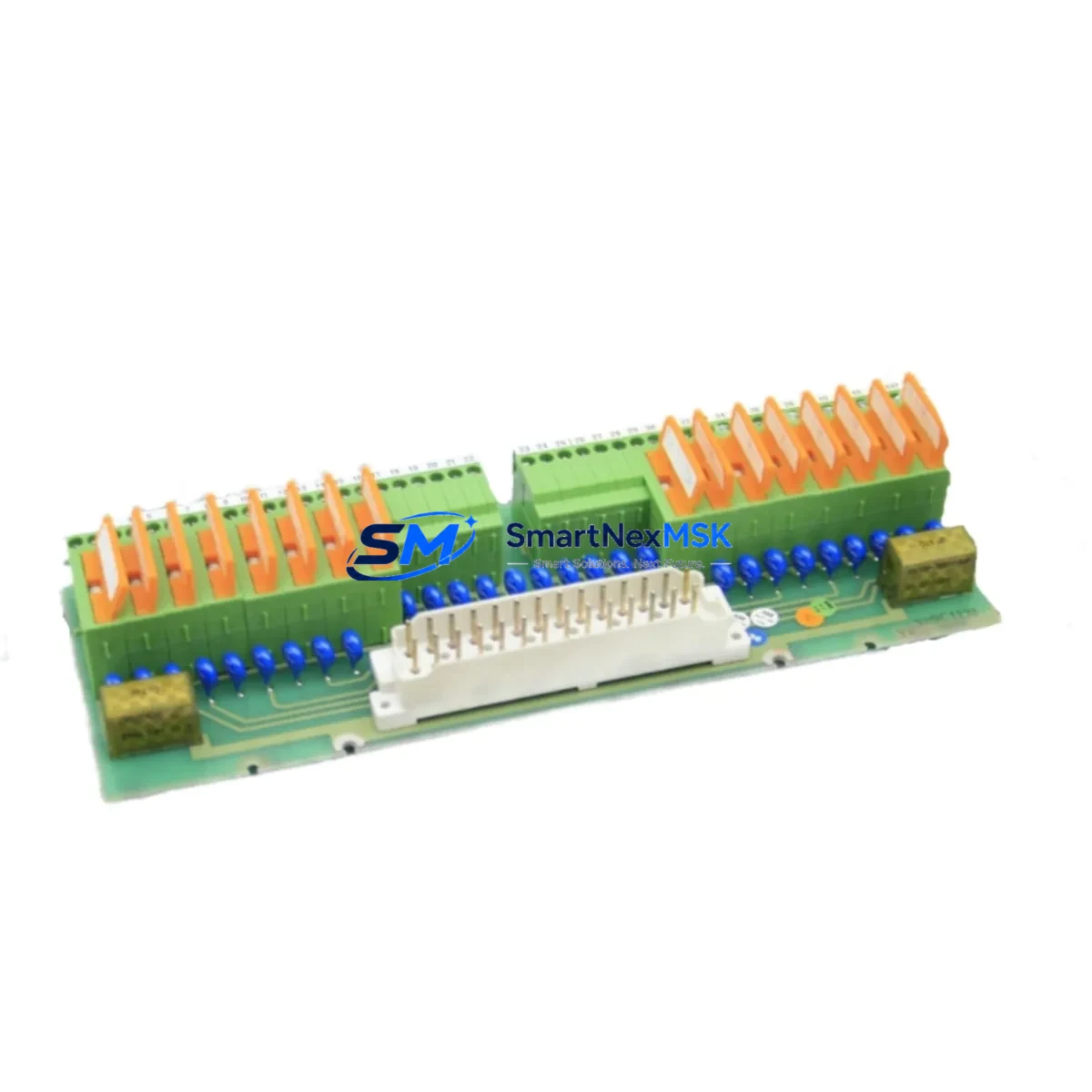
The ABB DSTD131 (57160001-HU) is an original DCS connection unit designed for the ABB Advant OCS MOD 300 distributed control system. As a critical interface module within the MOD 300 control architecture, the DSTD131 manages signal routing and I/O connectivity between field instruments and the process controller. For maintenance engineers managing aging Advant OCS installations, securing a tested, original DSTD131 spare is essential to minimizing unplanned downtime and sustaining long-term system reliability.
This unit is sourced as an original ABB component, fully inspected and function-tested prior to shipment. It is supplied with a 12-month warranty and is ready for immediate deployment in planned maintenance, emergency replacement, or spare parts inventory replenishment programs.
Spare Maintenance Table
| Parameter | Specification |
|---|---|
| Part Number | DSTD131 / 57160001-HU |
| Manufacturer | ABB (ASEA Brown Boveri) |
| Series / Platform | Advant OCS MOD 300 |
| Module Type | DCS Connection Unit |
| Origin | Sweden |
| Compatibility | ABB Advant OCS MOD 300 DCS systems; compatible with DSTD110, DSTD150, DSAX110 backplane configurations |
| Installation | Rack/backplane mount; standard MOD 300 subrack |
| Operating Environment | Industrial control cabinet; temperature 0–55°C, humidity 5–95% non-condensing |
| Condition | Original, tested, function-verified |
| Warranty | 12 Months |
| Lead Time | In stock — ships within 1–3 business days |
| Weight | 395 g |
Maintenance Planning for Continuous Operation
When a DSTD131 connection unit fails or is flagged during a scheduled inspection, the fault rarely exists in isolation. Experienced maintenance engineers know that a DCS connection unit fault in a MOD 300 system often signals stress across adjacent components in the same subrack or electrical loop. A thorough maintenance response should include inspection of the following associated components:
Begin with the DSAX110 analog I/O module and DSTD110 termination unit — both share the same backplane bus and are subject to the same environmental and electrical stresses as the DSTD131. Check the DSDO115 digital output module for contact wear if the DSTD131 was involved in discrete output circuits. Inspect the DSMB175 processor module for firmware integrity and communication status, as a degraded connection unit can generate spurious faults that propagate to the CPU layer.
On the power side, verify the DSDP140 power supply module output voltage stability — undervoltage conditions are a leading cause of premature connection unit failure in MOD 300 cabinets. Check all terminal blocks and field wiring terminations for corrosion, loose connections, or insulation breakdown, particularly in high-humidity or chemically aggressive environments. If the system includes DSTD150 signal conditioning units or DSAI130 analog input modules, these should be included in the same inspection cycle.
For systems with serial or fieldbus communication, inspect the DSSB110 communication interface module and associated cabling for signal integrity. Where signal isolation is required between field instruments and the DCS, verify that any installed signal isolators or galvanic separators are within calibration and showing no drift. Finally, review the DSRF180 relay output module if the DSTD131 was part of a relay-driven interlock or safety loop — relay contact degradation is a common co-failure mode.
Maintaining a structured spare parts kit that includes the DSTD131 alongside these complementary modules significantly reduces mean time to repair (MTTR) and supports a proactive maintenance posture for aging MOD 300 installations.
Site Replacement Workflow
Replacing the DSTD131 57160001-HU on a live MOD 300 system requires a structured approach to avoid introducing new faults or extending downtime. Follow this recommended workflow:
1. Pre-replacement verification: Confirm the replacement unit’s part number and hardware revision against the installed unit. The DSTD131 57160001-HU is a specific hardware variant — substituting an incompatible revision may cause communication errors or I/O mapping faults. Cross-reference the system’s hardware configuration database (HCD) before proceeding.
2. Safe isolation: Place the affected loop or subrack in manual control or bypass mode via the operator station. Notify the control room before removing any module. Document the current I/O status and any active alarms.
3. Module extraction and installation: Power down the subrack if hot-swap is not supported for this module type. Remove the DSTD131 by releasing the front panel locking mechanism and sliding the module out of the backplane. Insert the replacement unit, ensuring full backplane connector engagement. Restore subrack power.
4. Post-installation verification: Monitor the system for communication re-establishment, I/O status normalization, and absence of new fault codes. Verify field signal readings against known-good reference values. Confirm that the replacement unit is recognized by the MOD 300 controller and that no hardware mismatch alarms are generated.
5. Documentation and spare replenishment: Update the maintenance log with the replacement date, unit serial number, and post-installation test results. Immediately initiate a reorder for the consumed spare to maintain inventory depth. For critical MOD 300 installations, a minimum of one DSTD131 spare per active subrack is recommended.
Spare Parts Support FAQ
Q: Is this DSTD131 an original ABB component or a third-party replacement?
A: This is an original ABB DSTD131 57160001-HU unit. We do not supply third-party replicas or remanufactured substitutes. All units are sourced from verified industrial channels and are function-tested before shipment.
Q: What does the 12-month warranty cover?
A: The 12-month warranty covers functional failure under normal operating conditions. If the unit fails to perform its specified function within the warranty period, we will provide a replacement or full refund. The warranty does not cover damage caused by incorrect installation, overvoltage, or physical mishandling.
Q: How do I verify compatibility before installation?
A: Confirm the part number (DSTD131) and hardware suffix (57160001-HU) against your system’s hardware configuration database or the existing installed unit’s label. If you are unsure, contact our technical team with your MOD 300 system configuration details and we will confirm compatibility before shipment.
Q: What is your typical lead time and how are units tested before shipping?
A: In-stock units ship within 1–3 business days. Each unit undergoes visual inspection, connector integrity check, and functional verification prior to packaging. Units are shipped in anti-static packaging with appropriate cushioning to prevent transit damage.
© 2026 SMARTNEXMSK. All rights reserved.
Original Source: https://smartnexmsk.com
Contact: sales@smartnexmsk.com | +86 18259474341


