ABB FF1000R17R121 Maintenance-Ready Spare for HiPak Automation
The ABB FF1000R17R121 is a high-power HiPak IGBT module rated at 1700 V and 1000 A, engineered for demanding industrial automation environments including medium-voltage drives, traction converters, UPS systems, and large-scale power conditioning equipment. For maintenance engineers managing aging drive cabinets or planning scheduled overhauls, holding a verified original spare of the FF1000R17R121 is a critical element of any downtime-reduction strategy. Unplanned IGBT failure in a high-current inverter stage can halt production lines for days; a pre-qualified, tested replacement on the shelf reduces mean time to repair (MTTR) to hours.
This listing supplies the FF1000R17R121 as an original ABB HiPak series component, sourced through established industrial channels, individually inspected, and shipped with full electrical test documentation. Each unit carries a 12-month warranty covering manufacturing defects and parametric conformance, giving procurement engineers the confidence to approve the purchase as a long-term inventory asset rather than a one-off emergency buy.
Spare Maintenance Table
| Parameter | Specification |
|---|---|
| Part Number | FF1000R17R121 |
| Brand / Series | ABB / HiPak |
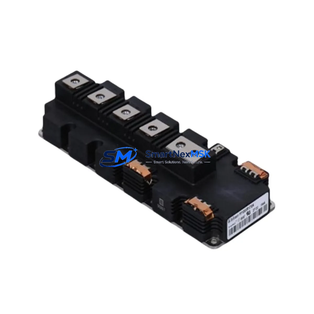
| Module Type | IGBT Power Module (Dual) |
| Collector-Emitter Voltage (VCES) | 1700 V |
| Collector Current (IC) | 1000 A |
| Gate-Emitter Voltage (VGE) | ±20 V |
| Package / Footprint | HiPak 2 (140 × 130 mm baseplate) |
| Thermal Resistance (Rth(j-c)) | ≤ 0.025 K/W per IGBT |
| Operating Junction Temp. | −40 °C to +150 °C |
| Isolation Voltage | 6000 Vrms |
| Country of Origin | Germany |
| Compatibility | ABB ACS800, ACS2000, ACS6000, PCS6000 series; compatible inverter bridges using HiPak 2 footprint |
| Application Environment | Medium-voltage drives, traction, wind converters, industrial UPS, power conditioning |
| Mounting | Baseplate bolted to heatsink; torque per ABB datasheet (typically 6–8 N·m) |
| Maintenance Recommendation | Replace thermal interface material (TIM) on every module swap; re-torque to spec; verify gate driver output before energising |
| Warranty | 12 Months — covers manufacturing defects and parametric conformance |
| Shipping | Anti-static packaging; insured express freight; electrical test report included |
Maintenance Planning for Continuous Operation
A disciplined maintenance plan for any system housing the FF1000R17R121 extends well beyond the IGBT module itself. When a maintenance or procurement engineer schedules a module replacement, the surrounding components in the same inverter leg and control cabinet should be evaluated concurrently to avoid repeat outages.
Gate Driver Boards: The gate driver board that interfaces directly with the FF1000R17R121 gate-emitter terminals is subject to the same thermal cycling stress as the module. Inspect the ABB AGDR-81C or equivalent gate driver card for solder joint fatigue, optocoupler degradation, and supply rail voltage drift. A failed gate driver after a fresh IGBT installation is a common and avoidable cause of secondary downtime.
DC Bus Capacitor Banks: Electrolytic capacitors in the DC link age independently of the IGBT. Measure capacitance and ESR during the planned outage window. Capacitor banks in ACS800 or ACS2000 cabinets that are approaching end-of-life will stress the new module with voltage spikes if left unaddressed.
Snubber and Clamp Circuits: Check snubber capacitors and resistors mounted near the module baseplate. Degraded snubbers allow dV/dt transients that can exceed the FF1000R17R121’s rated VCES under fault conditions.
Current Sensors and Hall-Effect Transducers: The current feedback loop depends on accurate transducer readings. A drifting LEM or ABB current transducer will cause the drive controller to misinterpret load current, potentially triggering nuisance overcurrent trips on the new module.
Control Power Supply Modules: The 24 V DC SMPS units powering the gate drivers, I/O cards, and communication modules should be load-tested. An intermittent control supply is a frequent root cause of unexplained IGBT gate faults.
I/O and Signal Isolation Modules: Analogue and digital I/O modules in the same control cabinet — particularly those handling speed reference, torque limit, and fault relay signals — should be inspected for contact wear and insulation resistance. Signal isolation barriers between the PLC and the drive control board prevent ground-loop interference that can corrupt gate timing.
Relay and Contactor Assemblies: Pre-charge contactors, main contactors, and bypass relays in the drive cabinet accumulate contact wear proportional to switching cycles. Inspect contact surfaces and coil resistance; replace any contactor showing pitting or coil resistance deviation greater than 10%.
Terminal Blocks and Bus Bars: Thermal cycling causes micro-movement in bolted connections. Re-torque all power terminal connections on the DC bus bars and AC output terminals to the manufacturer’s specification during the same maintenance window.
Thermal Interface Material: Always replace the thermal grease or phase-change pad between the FF1000R17R121 baseplate and the heatsink. Reusing aged TIM is one of the most common causes of premature module failure after a swap.
Communication and Fieldbus Modules: PROFIBUS, PROFINET, or Modbus RTU communication cards installed in the drive should be checked for firmware currency and connector integrity. A communication fault after module replacement — caused by an unrelated card — can be misdiagnosed as a drive hardware issue, wasting valuable commissioning time.
Site Replacement Workflow
1. Pre-Outage Preparation: Confirm the replacement FF1000R17R121 part number, date code, and test report against the installed unit’s nameplate. Verify that the gate driver board firmware and parameter set are backed up. Gather torque wrench, TIM applicator, anti-static wrist strap, and insulation resistance tester before the outage window opens.
2. Safe Isolation: Follow the site LOTO (Lock-Out/Tag-Out) procedure. Discharge the DC bus capacitors fully — measure with a calibrated meter before touching any bus bar. Confirm zero voltage on all phases.
3. Module Removal: Disconnect gate driver connectors, then power terminals. Remove baseplate bolts in the sequence specified in the ABB HiPak installation guide. Lift the module straight up to avoid stress on the ceramic substrate.
4. Heatsink Inspection and Preparation: Clean the heatsink contact surface with isopropyl alcohol. Inspect for corrosion, warping, or debris. Apply fresh TIM evenly across the baseplate contact area of the new FF1000R17R121.
5. Module Installation: Lower the new module onto the heatsink, align mounting holes, and torque bolts in a cross pattern to the specified value. Reconnect power terminals first, then gate driver connectors. Verify connector locking clips are fully engaged.
6. Pre-Energisation Checks: Measure gate-emitter resistance on all channels with a multimeter (should read open circuit with no gate drive applied). Perform an insulation resistance test between the DC bus and chassis at 500 V DC. Confirm control supply voltages are within tolerance.
7. Commissioning: Restore control power only. Verify gate driver self-test passes and no fault codes are active. Apply main power at reduced load. Monitor heatsink temperature, output current waveform, and DC bus voltage during the first 30 minutes of operation before returning to full production load.
This systematic approach minimises the risk of repeat failures, validates the replacement, and provides a documented record for the maintenance log — supporting both internal audits and warranty claims.
Spare Parts Support FAQ
Q1: What is the expected service life of the FF1000R17R121, and when should I plan a proactive replacement?
ABB HiPak IGBT modules are designed for long service life under rated conditions, but thermal cycling, overload events, and ambient contamination accelerate ageing. In high-cycle applications such as crane drives or compressor drives, proactive replacement at 8–12 years of service — or after any recorded overcurrent event exceeding 150% rated current — is a prudent strategy. Condition monitoring via thermal imaging of the heatsink and periodic gate threshold voltage measurement can extend replacement intervals with confidence.
Q2: How do I verify compatibility before installing the FF1000R17R121 in my existing drive cabinet?
Confirm the HiPak 2 footprint (140 × 130 mm baseplate), 1700 V / 1000 A ratings, and gate driver interface voltage against your drive’s schematic. Cross-reference the ABB drive model number — ACS800, ACS2000, or equivalent — with the ABB spare parts list for that platform. If the installed unit carries a different date code or minor revision suffix, contact our technical team with the full nameplate data for a compatibility confirmation before ordering.
Q3: What pre-shipment testing is performed on each FF1000R17R121 unit?
Every unit undergoes static electrical testing covering VCE(sat), leakage current (ICES), gate threshold voltage (VGE(th)), and isolation voltage. Test results are documented and shipped with the module. Units that fail any parameter are quarantined and not dispatched. This process ensures that the module you receive performs within ABB’s published datasheet limits from day one.
Q4: What does the 12-month warranty cover, and how is a warranty claim processed?
The 12-month warranty covers manufacturing defects and parametric non-conformance under normal operating conditions. It does not cover damage resulting from incorrect installation, overvoltage events beyond rated VCES, or operation without adequate thermal management. To initiate a claim, contact sales@smartnexmsk.com with the order number, installation date, fault description, and any available drive fault log. Our team will assess the claim and arrange replacement or credit within 5 business days of receiving the returned unit.
© 2026 SMARTNEXMSK. All rights reserved.
Original Source: https://smartnexmsk.com
Contact: sales@smartnexmsk.com | +86 18259474341


