ABB FS225R12KE3/AGDR-71C S Maintenance-Ready Spare for AGDR Automation
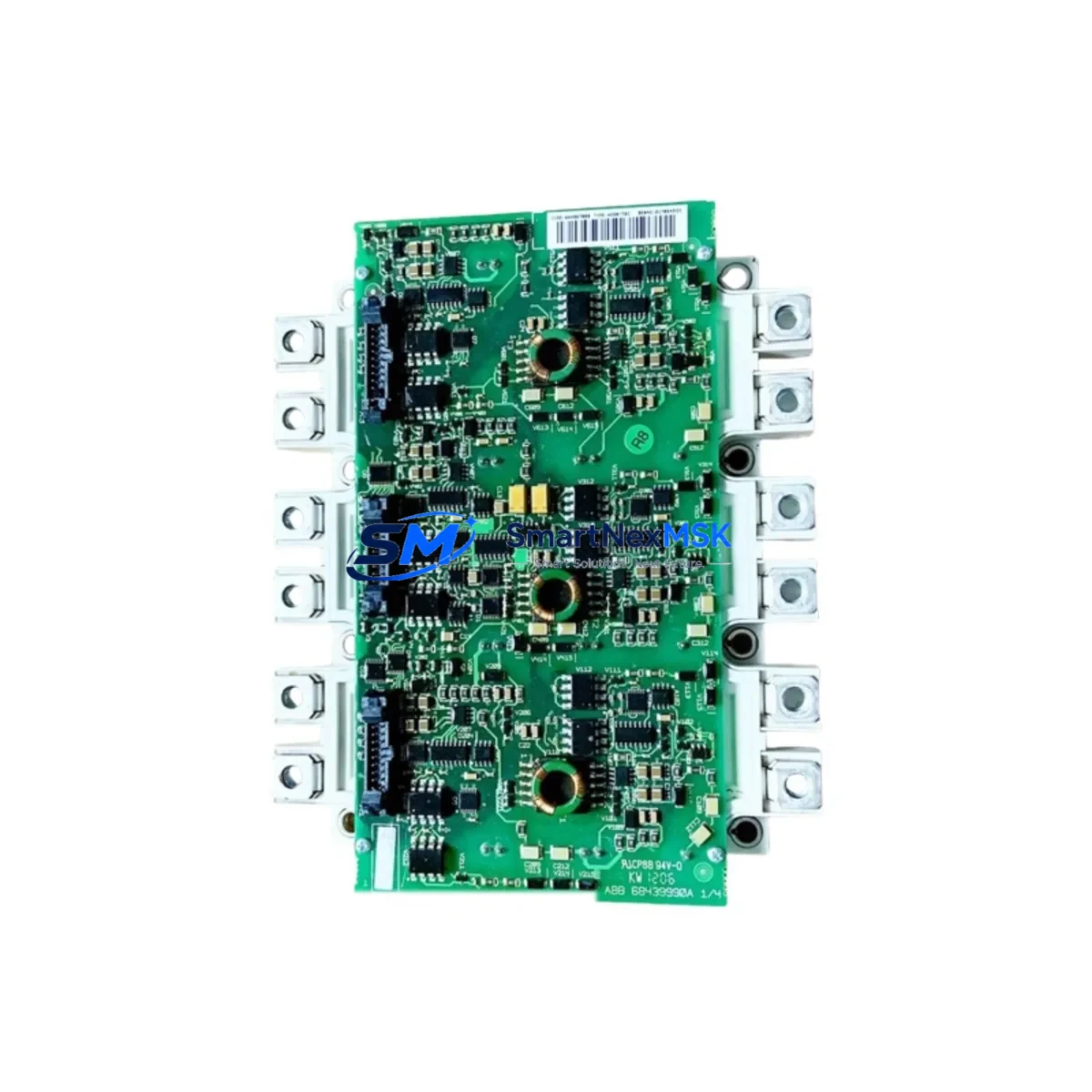
The ABB FS225R12KE3/AGDR-71C S is an original IGBT gate driver board engineered for high-reliability industrial drive systems. Designed as a direct replacement component within ABB’s AGDR gate driver series, this board plays a critical role in controlling IGBT switching in medium-to-high power variable frequency drives including the ACS800 and ACS880 series. For maintenance engineers managing aging drive cabinets or executing planned overhauls, having a verified spare of this board on hand is essential to minimizing unplanned downtime and restoring production continuity within hours rather than days.
This spare is sourced as an original ABB component, manufactured in Germany, and has undergone functional testing prior to dispatch. Each unit ships with a 12-month warranty covering manufacturing defects and functional failures under normal operating conditions. Whether you are responding to an emergency drive fault, executing a scheduled preventive maintenance cycle, or building a critical spare inventory for a multi-drive installation, the FS225R12KE3/AGDR-71C S provides the compatibility assurance and quality confidence that industrial procurement and maintenance teams require.
Spare Maintenance Table
| Parameter | Specification |
|---|---|
| Part Number / SKU | FS225R12KE3/AGDR-71C S |
| Brand | ABB |
| Series | AGDR Gate Driver Series |
| Component Type | IGBT Gate Driver Board |
| Compatible Drive Series | ABB ACS800, ACS880, ACS600 (AGDR-configured) |
| IGBT Module Compatibility | FS225R12KE3 (1200V / 225A IGBT module) |
| Rated Voltage | 1200 V (IGBT blocking voltage) |
| Gate Drive Output | ±15V gate signal, isolated per phase |
| Isolation | Galvanic isolation between control and power stage |
| Mounting | Direct-mount to IGBT module, AGDR bracket compatible |
| Operating Temperature | -10°C to +55°C (ambient, forced-air cooled cabinet) |
| Country of Origin | Germany (DE) |
| Condition | Original, New / Tested Surplus |
| Warranty | 12 Months from date of shipment |
| Lead Time | In stock — ships within 1–3 business days |
| Application Environment | Industrial drive cabinets, motor control centers, process automation |
Maintenance Planning for Continuous Operation
When a gate driver board such as the FS225R12KE3/AGDR-71C S fails or shows signs of degradation — including erratic drive faults, IGBT overcurrent trips, or asymmetric phase output — the replacement process should be treated as a system-level maintenance event, not an isolated component swap. Experienced maintenance engineers know that a gate driver failure is often symptomatic of broader stress conditions within the drive cabinet, and a thorough inspection of surrounding components is essential before returning the drive to service.
Begin by inspecting the IGBT power module (FS225R12KE3) itself. Gate driver failures can be caused by IGBT degradation, so verifying the module’s gate-emitter resistance and collector-emitter saturation voltage before installing a new driver board is critical. If the IGBT module shows signs of thermal stress or internal short, it must be replaced concurrently.
Next, check the DC bus capacitor bank and DC bus voltage measurement board. Overvoltage transients on the DC link are a leading cause of gate driver stress. Capacitors with elevated ESR or reduced capacitance can no longer suppress voltage spikes effectively, accelerating gate driver wear. Alongside this, inspect the brake chopper module and braking resistor circuit — a failed chopper can allow DC bus overvoltage events that repeatedly stress the gate driver.
The fiber optic interface board (commonly the AINT or RDCU control board in ACS800 systems) should also be verified. Gate driver boards in the AGDR series receive switching commands via fiber optic links; a degraded fiber connection or contaminated optical port can cause missed gate pulses, leading to shoot-through faults that destroy gate drivers. Clean and test all fiber optic cables and connectors as part of this maintenance event.
Inspect the 24VDC auxiliary power supply feeding the control electronics. Voltage ripple or dropout on the auxiliary rail can cause erratic gate driver behavior even when the driver board itself is functional. Use an oscilloscope to verify supply stability under load. Similarly, check the fan and cooling system — thermal management is directly linked to gate driver longevity, and a partially blocked heat sink or failing cooling fan will shorten the service life of any replacement board.
For drives integrated into larger process control systems, verify the I/O interface module and fieldbus communication adapter (such as the RPBA-01 PROFIBUS adapter or RCAN-01 CANopen module) are functioning correctly. A communication fault that causes the drive to receive incorrect speed references can result in abnormal load cycles that stress power electronics. Finally, review the terminal block wiring and control cable shielding within the cabinet — poor shielding on signal cables running near power conductors is a common source of EMI-induced gate driver faults in older installations.
Site Replacement Workflow
Replacing the FS225R12KE3/AGDR-71C S in the field follows a structured procedure to ensure safe installation, system compatibility, and minimal downtime. Before beginning, isolate the drive from mains power and verify zero voltage on the DC bus using a calibrated multimeter — DC bus capacitors can retain dangerous charge for several minutes after power-off.
Document the existing gate driver board’s position, fiber optic connections, and any DIP switch or jumper settings before removal. Photograph the wiring harness and connector orientation. The AGDR-71C S board connects directly to the IGBT module gate pins and to the fiber optic interface; ensure the replacement board’s connector alignment matches the original before applying any mechanical pressure.
After installing the new board, perform a low-voltage power-up test with the motor disconnected. Verify that the drive control board (RDCU or equivalent) recognizes the gate driver and that no fault codes related to gate driver communication or IGBT status are present. Run a short no-load test at low frequency before reconnecting the motor load. This workflow reduces the risk of a repeat failure and confirms system compatibility before full production restart.
For legacy ACS800 installations where the original AGDR-71C S may no longer be available through standard distribution channels, this original spare provides a direct form-fit-function replacement that preserves the existing drive configuration without requiring firmware updates or parameter re-commissioning. This is particularly valuable in facilities where the drive is integrated into a DCS or SCADA system and re-commissioning would require significant engineering resources.
Spare Parts Support FAQ
Q1: Is the FS225R12KE3/AGDR-71C S compatible with all ACS800 drive variants?
The AGDR-71C S gate driver board is designed for use with the FS225R12KE3 IGBT module (1200V/225A) and is compatible with ACS800 and ACS880 drive frames that use this specific IGBT module. Compatibility depends on the drive frame size and IGBT module type — always verify the IGBT module part number in your drive before ordering. Our technical team can assist with compatibility confirmation based on your drive nameplate data.
Q2: What testing is performed before shipment?
Each FS225R12KE3/AGDR-71C S unit undergoes functional verification prior to dispatch, including gate signal output testing and isolation resistance checks. Units sourced as new original stock are verified against ABB factory specifications. All units are shipped with anti-static packaging and include a 12-month warranty covering functional defects under normal operating conditions.
Q3: How should I manage spare inventory for AGDR gate driver boards in a multi-drive facility?
For facilities operating three or more ACS800 or ACS880 drives using the FS225R12KE3 IGBT module, maintaining at least one FS225R12KE3/AGDR-71C S spare on-site is strongly recommended. Gate driver boards are a high-criticality spare due to their direct role in drive operation and the potential for extended lead times on legacy components. A spare holding strategy aligned with your planned maintenance intervals — typically 12 to 24 months — ensures rapid response capability for both emergency and scheduled replacement scenarios.
Q4: Can this board replace an older AGDR-71C (without the ‘S’ suffix) in an existing installation?
The ‘S’ suffix typically denotes a revised or enhanced version of the AGDR-71C board. In most cases, the AGDR-71C S is backward compatible with installations originally fitted with the AGDR-71C, as ABB designs successor boards to maintain form-fit-function compatibility within the same IGBT module family. However, we recommend confirming compatibility with your drive’s service documentation or contacting our technical support team before installation in a critical application.
© 2026 SMARTNEXMSK. All rights reserved.
Original Source: https://smartnexmsk.com
Contact: sales@smartnexmsk.com | +86 18259474341


