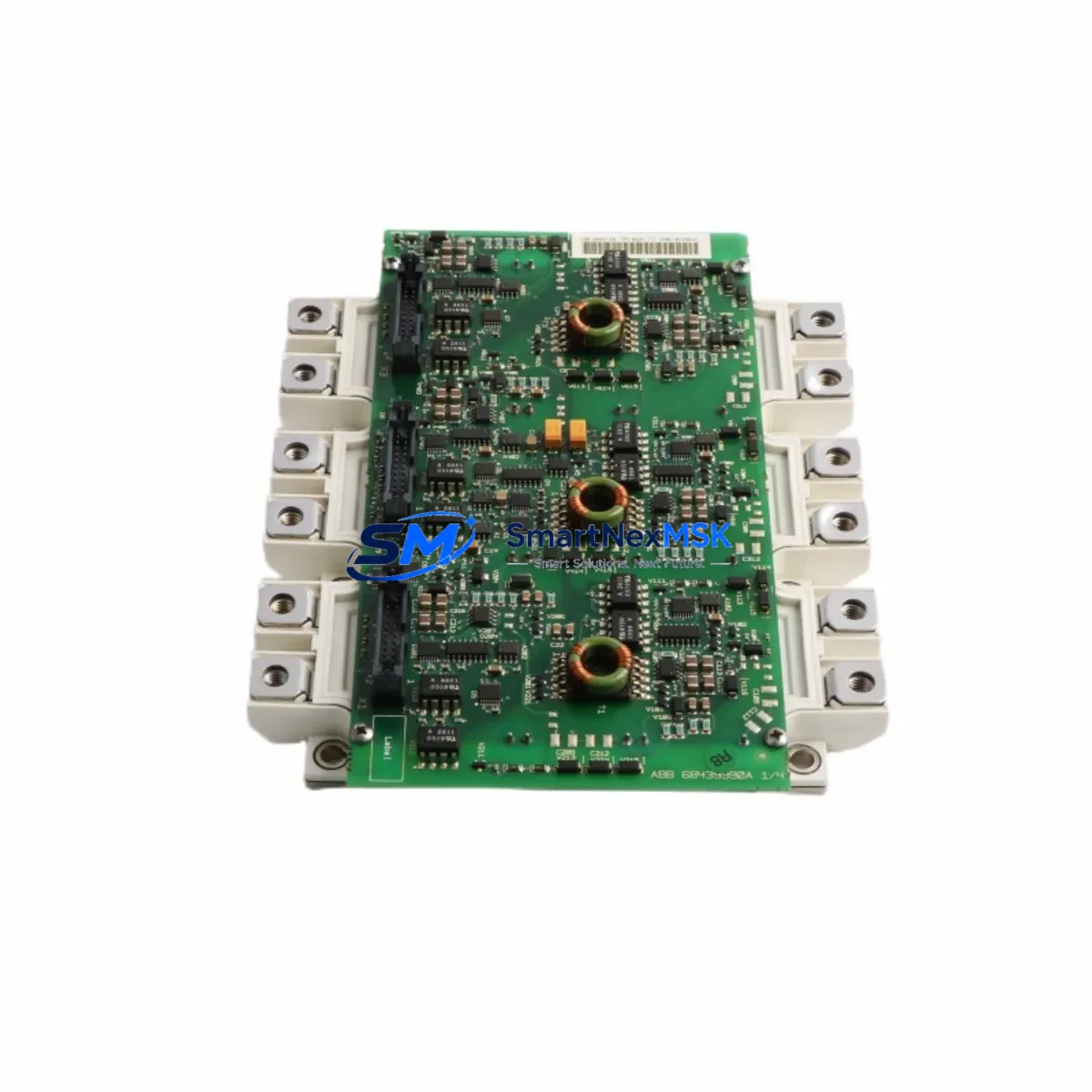
ABB FS450R12KE3/AGDR-71C Retrofit-Ready IGBT Module for EconoPACK Control Systems
The ABB FS450R12KE3/AGDR-71C is a Six-Pack IGBT power module rated at 1200V / 450A, engineered for high-performance variable frequency drive (VFD) applications within ABB’s EconoPACK platform. As legacy ACS800 and ACS600 series drives reach end-of-service milestones, this module has become the primary retrofit and replacement solution for industrial facilities seeking to extend drive service life, reduce unplanned downtime, and avoid full drive replacement costs. Whether you are managing a planned upgrade cycle or responding to an emergency power module failure, the FS450R12KE3/AGDR-71C provides a verified, drop-in compatible path forward.
Upgrade Compatibility Table
| Parameter | Details |
|---|---|
| SKU / Part Number | FS450R12KE3/AGDR-71C |
| Voltage Rating | 1200V |
| Current Rating | 450A |
| Module Configuration | Six-Pack (3-phase bridge) |
| Gate Driver | AGDR-71C integrated |
| Compatible Drive Series | ABB ACS800, ACS600, ACS880 (select frames) |
| Mounting Interface | EconoPACK standard footprint |
| Communication Compatibility | DDCS fiber optic, RDCO-0x, RDCO-03 adapter boards |
| Replacement Recommendation | Direct replacement for FS300R12KE3 (300A) in uprated applications; cross-compatible with FS450R12KE3 base module |
| Commissioning Notes | Verify gate driver supply voltage (±15V), thermal paste application, and torque spec on bus bar terminals |
| Warranty | 12-Month Warranty — covers manufacturing defects and functional failure under rated operating conditions |
Retrofit Planning for Existing Automation Systems
Replacing the FS450R12KE3/AGDR-71C in an existing ACS800 or ACS600 drive cabinet requires a structured approach to ensure electrical compatibility and minimize commissioning risk. Before removing the failed module, engineers should document the existing DC bus voltage, verify that the AGDR-71C gate driver board is receiving the correct ±15V auxiliary supply from the drive’s APOW-01 power supply board, and confirm that the fiber optic connections to the AINT-02 or AINT-14 inverter control board are intact and correctly routed.
The physical installation follows the EconoPACK mounting standard: the module seats onto a copper-base heatsink with M6 fasteners, and the DC bus bars connect via bolted terminals requiring precise torque (typically 6–8 Nm) to avoid contact resistance issues. Thermal interface material must be reapplied using a certified phase-change pad or high-conductivity paste to maintain junction-to-case thermal resistance within ABB’s specified limits.
For sites running the ACS800 with an RDCO-03 DDCS communication adapter, the fiber optic ring topology connecting the drive to an AC800M controller or a Symphony Plus DCS node must be re-verified after module swap. Any interruption in the DDCS ring will prevent the drive from receiving speed references or fault acknowledgments from the upper control layer. Similarly, if the drive is integrated into a Profibus DP network via an RPBA-01 adapter, the node address and baud rate settings stored in the drive’s parameter group 51 must be confirmed post-replacement.
I/O wiring at the AITC-02 or AIMA-01 analog I/O extension modules should be checked for correct signal levels before re-energizing. In multi-drive systems sharing a common DC bus, the BAMU-01 bus adapter module and associated pre-charge circuit must be inspected to ensure the replacement module does not experience inrush stress during initial power-up. For drives equipped with an ACS800 brake chopper unit (NBRA-6xx series), the chopper threshold parameters should be re-confirmed to protect the new IGBT module during regenerative braking events.
HMI panels connected via the CDP312R control panel or remote panel link should display correct drive status within seconds of successful commissioning. If the ACS800 is supervised by an ABB Ability™ Drive Advisor or a legacy DriveWindow Light PC tool, a full parameter upload should be performed after replacement to confirm that no parameter corruption occurred during the fault event that caused the original module failure.
Downtime Control During System Migration
Minimizing production downtime during an IGBT module replacement on an ACS800 or ACS600 drive requires pre-staging the replacement FS450R12KE3/AGDR-71C before the maintenance window begins. All replacement modules shipped from our inventory are pre-tested under load conditions and include a factory test report, reducing on-site verification time significantly.
The recommended procedure is to perform a full parameter backup using DriveWindow or the CDP312R panel before de-energizing the drive. This preserves the motor control macro, speed reference scaling, PID tuning parameters, and all application-specific settings stored in the APBU-44 pulse encoder interface or RTAC-01 tacho adapter if fitted. Once the replacement module is installed and the drive is re-energized, the parameter set can be restored in minutes, avoiding the need for a full recommissioning cycle.
For critical continuous-process applications — such as pump drives in water treatment, fan drives in HVAC systems, or conveyor drives in material handling — a cold standby drive strategy using a pre-configured ACS800 spare frame with the FS450R12KE3/AGDR-71C already installed can reduce switchover time to under 30 minutes. This approach preserves original program logic, maintains HMI screen continuity, and keeps the DDCS or Profibus communication link active with minimal reconfiguration.
All modules are dispatched with full ESD packaging, individual serial number traceability, and a 12-month warranty covering functional failure under rated operating conditions. Express shipping options are available for emergency breakdown situations, with same-day dispatch for in-stock units confirmed before 14:00 CST.
Retrofit Support FAQ
Q1: Is the FS450R12KE3/AGDR-71C a direct drop-in replacement for the FS300R12KE3 in ACS800 drives?
A: The FS450R12KE3/AGDR-71C shares the same EconoPACK footprint and gate driver interface as the FS300R12KE3, making it physically compatible. However, the 450A current rating represents an uprate from the 300A module. Before installation, verify that the drive’s thermal management system and DC bus fusing are rated for the higher current capacity. In most ACS800 frame sizes, this uprate is within the drive’s design margin and is acceptable for retrofit use.
Q2: What wiring changes are required when replacing the AGDR-71C gate driver board?
A: The AGDR-71C gate driver is integrated with the FS450R12KE3 module as a combined assembly. No separate gate driver wiring changes are required beyond reconnecting the existing fiber optic cables from the AINT-02 inverter control board and confirming the ±15V auxiliary supply from the APOW-01 board. Polarity and connector orientation should be verified against the ACS800 hardware manual before energizing.
Q3: How is compatibility verified before shipment?
A: Each FS450R12KE3/AGDR-71C unit undergoes functional testing including gate signal integrity verification, insulation resistance testing at 2500V DC, and thermal cycling validation. A test report is included with every shipment. Units are serialized and traceable to batch production records, supporting quality audit requirements in ISO 9001-certified facilities.
Q4: What does the 12-month warranty cover?
A: The 12-month warranty covers manufacturing defects, gate driver failure, and functional failure under rated operating conditions (1200V / 450A, within specified junction temperature limits). Warranty claims are supported with return merchandise authorization (RMA) processing, and replacement units are dispatched within 3 business days of fault confirmation. Damage caused by incorrect installation, overvoltage events, or operation outside rated parameters is excluded.
© 2026 SMARTNEXMSK. All rights reserved.
Original Source: https://smartnexmsk.com
Contact: sales@smartnexmsk.com | +86 18259474341


