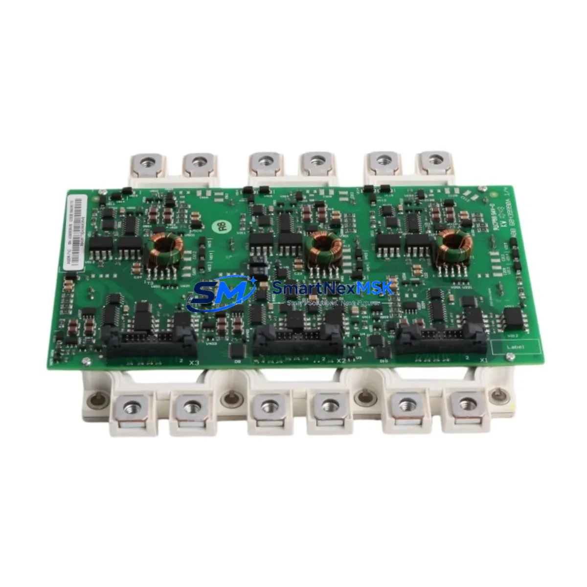
ABB FS450R17KE3/AGDR-71C Retrofit-Ready IGBT Gate Driver for ACS800/ACS880 Control Systems
The ABB FS450R17KE3/AGDR-71C is a high-performance IGBT gate driver module engineered for seamless compatibility with ABB’s ACS800 and ACS880 series variable frequency drives. Designed to serve as a direct retrofit replacement for aging or discontinued gate driver assemblies, this module enables industrial facilities to extend the operational life of existing drive cabinets without requiring a full system overhaul. Whether you are managing a planned upgrade cycle or responding to an unplanned failure, the FS450R17KE3/AGDR-71C delivers the electrical performance, mechanical fit, and firmware compatibility required for a smooth, low-risk transition.
This module is sourced from verified supply channels, 100% functionally tested prior to shipment, and backed by a 12-month warranty. Stock is available for immediate dispatch, supporting both emergency replacement scenarios and scheduled maintenance windows.
Upgrade Compatibility Table
| Parameter | Details |
|---|---|
| Compatible Drive Series | ABB ACS800, ACS880 |
| Module Type | IGBT Gate Driver (Power Interface Module) |
| Voltage Class | 1700 V (17KE series) |
| Current Rating | 450 A |
| Backplane / Rack Interface | Direct plug-in to ACS800/ACS880 IGBT power stack; no adapter required |
| Communication Compatibility | Compatible with RDCO-03/04 DDCS fiber-optic communication boards |
| Installation Requirement | DIN rail or panel-mount; torque spec per ABB service manual |
| Replacement Recommendation | Direct drop-in for FS450R17KE3/AGDR-71C OEM assemblies; verify firmware revision on RMIO board |
| Commissioning Focus | Gate signal timing verification, DC bus pre-charge sequence, fault log reset via DriveWindow or CDP control panel |
| Warranty | 12 months from date of shipment; covers manufacturing defects and functional failure under normal operating conditions |
Retrofit Planning for Existing Automation Systems
Replacing the FS450R17KE3/AGDR-71C within an active production environment requires careful pre-planning to ensure continuity of the control architecture. In most ACS800 and ACS880 installations, the gate driver module interfaces directly with the RMIO-11C or RMIO-02C control board, which manages motor control logic, parameter sets, and fault history. Before initiating the swap, engineers should back up all drive parameters using DriveWindow Light or the CDP control panel to prevent loss of tuned PID loops, ramp times, and application macros.
Power supply verification is a critical first step. The AGDR-71C gate driver requires a stable auxiliary 24 VDC supply from the APBU-44C or APBU-12C power distribution board. Confirm that the auxiliary power rail is within tolerance before energizing the new module. Inspect the DC bus capacitor bank condition — in drives that have been in service for more than eight years, capacitor reforming or replacement may be advisable before installing a new gate driver to avoid premature stress on the module.
Terminal wiring on the IGBT power stack must be inspected for oxidation, loose torque, or thermal damage. The gate driver connects to the IGBT module via a dedicated gate-emitter interface; any contamination or mechanical damage at this interface can cause erratic switching behavior or immediate fault trips. Use the ABB service manual torque specifications — typically 2.5 Nm for M5 terminals — and apply fresh thermal compound if the module is being reseated against a heatsink surface.
For facilities migrating from older ACS600 or ACS400 platforms to ACS800 or ACS880, the FS450R17KE3/AGDR-71C is frequently part of a broader upgrade that also involves replacing the RDCO-03 DDCS communication board, updating the RMIO firmware, and reconfiguring fieldbus adapters such as the RPBA-01 PROFIBUS adapter or RCAN-01 CANopen module. In these migration projects, the I/O terminal mapping between the old and new control boards must be carefully cross-referenced — particularly for digital inputs used for run/stop commands, fault reset, and speed reference selection.
HMI screen updates are often overlooked during gate driver replacements. If the facility uses an ABB Panel Builder or third-party SCADA system linked to the drive via Modbus RTU or PROFIBUS DP, verify that the drive node address and baud rate settings are preserved after the module swap. The RMIO board retains these settings in non-volatile memory, but a full parameter restore from backup is recommended to confirm integrity. Additionally, if the installation includes an AINT-02 or AINT-11 inverter control board in a multi-drive configuration, the fiber-optic DDCS ring topology should be re-verified after the replacement to ensure all nodes are communicating correctly.
For cabinet-level upgrades, the FS450R17KE3/AGDR-71C is commonly installed alongside replacement components including the APBU-44C auxiliary power board, BAMU-01 brake chopper unit, RDCO-04 DDCS communication board, and updated RMIO-11C control boards. In multi-axis systems, the AINT-02 inverter control interface and AIMA-01 motor adapter may also require firmware alignment to maintain synchronization across axes.
Downtime Control During System Migration
Minimizing production downtime during a gate driver replacement is achievable with structured preparation. The recommended approach is to complete all parameter backups, spare parts staging, and wiring documentation during a scheduled maintenance window — ideally during a planned shutdown rather than an emergency response. Having the FS450R17KE3/AGDR-71C pre-tested and on-site before the maintenance window begins reduces the critical-path replacement time to under two hours in most standard ACS800 cabinet configurations.
Before de-energizing the drive, confirm that the DC bus has fully discharged — typically indicated by the DC bus voltage LED on the APBU board dropping below 50 VDC. This is a mandatory safety step and should be verified with a calibrated multimeter regardless of indicator status. Once the module is installed, the initial power-up sequence should follow the ABB commissioning checklist: verify auxiliary power, check gate signal integrity with an oscilloscope if available, perform a no-load motor run at low speed, and confirm fault-free operation before returning the drive to full production load.
For facilities with redundant drive configurations, the switchover to the standby drive during the replacement window preserves production continuity. Document the exact parameter set of the active drive before switchover to ensure the replacement module is commissioned to identical settings. All functional tests — including emergency stop response, speed reference tracking, and fieldbus communication — should be completed before the standby configuration is released.
Our team provides pre-shipment functional testing documentation for every FS450R17KE3/AGDR-71C unit, including gate signal waveform verification and insulation resistance test results. This documentation supports your site acceptance testing process and reduces commissioning risk. Units are shipped with ESD-protective packaging and include a test report traceable to the serial number.
Retrofit Support FAQ
Q: Is the FS450R17KE3/AGDR-71C a direct replacement for the original ABB OEM assembly?
A: Yes. The FS450R17KE3/AGDR-71C is a direct form-fit-function replacement for the original OEM gate driver assembly used in ACS800 and ACS880 series drives. No mechanical modifications or adapter boards are required. Verify the RMIO firmware version is compatible with your drive’s software revision before installation.
Q: What wiring checks are required before installing the replacement module?
A: Inspect all gate-emitter interface connections for oxidation or mechanical damage. Verify the 24 VDC auxiliary supply from the APBU board is within ±5% tolerance. Check DC bus discharge status before handling any power components. Re-torque all terminal connections to ABB-specified values after installation.
Q: How do I verify communication compatibility after the replacement?
A: After installation, restore drive parameters from backup and verify fieldbus communication by checking the RDCO board status LEDs and confirming node address and baud rate settings. For PROFIBUS configurations using the RPBA-01 adapter, perform a GSD file re-import if the drive firmware version has changed. Run a full I/O function test before returning to production.
Q: What does the 12-month warranty cover?
A: The 12-month warranty covers manufacturing defects and functional failure under normal operating conditions from the date of shipment. Each unit is pre-tested and ships with a functional test report. Warranty claims are supported by our technical team — contact sales@smartnexmsk.com with the unit serial number and fault description to initiate a claim.
© 2026 SMARTNEXMSK. All rights reserved.
Original Source: https://smartnexmsk.com
Contact: sales@smartnexmsk.com | +86 18259474341


