ABB GDC806B01 Maintenance-Ready Spare for ACS800 Automation
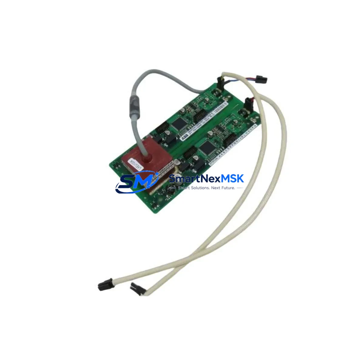
The ABB GDC806B01 (part number 3BHE036290R0001) is an original drive control board engineered for the ACS800 series variable frequency drive platform. In industrial facilities where ACS800 drives govern critical motor loads — compressors, pumps, conveyors, fans, and hoists — an unplanned control board failure can cascade into hours or days of unscheduled downtime. Stocking a verified GDC806B01 spare eliminates that risk and gives maintenance teams the confidence to execute rapid, same-shift board swaps without waiting on lead times from the OEM supply chain.
This board serves as the central intelligence of the ACS800 drive, managing pulse-width modulation output, IGBT gate drive signals, fault diagnostics, and fieldbus communication handshaking. When a GDC806B01 fails, symptoms typically include drive fault codes (e.g., FF52, FF61, or communication loss alarms), erratic speed reference tracking, or complete drive lockout. Having a pre-tested replacement on the shelf means engineers can isolate the fault, swap the board, and restore motor control within a single maintenance window.
Spare Maintenance Table
| Parameter | Specification |
|---|---|
| Part Number | GDC806B01 / 3BHE036290R0001 |
| Brand | ABB |
| Compatible Series | ACS800 Variable Frequency Drive |
| Board Function | Drive Control Board (Main Control) |
| Supply Voltage (Logic) | +5 VDC / ±15 VDC (internal SMPS) |
| Communication Interfaces | DDCS fiber optic, RDCO adapter slot |
| I/O Support | Digital I/O, Analog I/O via RMIO interface |
| Operating Temperature | 0 °C to +55 °C (ambient, drive cabinet) |
| Origin | Germany |
| Weight | 350 g |
| Warranty | 12 Months |
| Condition | Original Spare — Tested Before Shipment |
| Application | Industrial MRO, Planned Maintenance, Emergency Replacement |
Maintenance Planning for Continuous Operation
A GDC806B01 replacement should never be treated in isolation. When a maintenance or procurement engineer schedules a control board swap on an ACS800 drive, the surrounding components in the same control cabinet and electrical circuit deserve simultaneous inspection to prevent repeat failures and maximize the value of the planned outage window.
Begin with the RMIO-11C or RMIO-02C I/O board, which interfaces directly with the GDC806B01 and handles all analog and digital signal conditioning. A degraded RMIO board can corrupt speed references or cause spurious fault trips even after a clean control board replacement. Inspect the RDCO-01 or RDCO-02 DDCS communication adapter for fiber optic connector contamination or cracked ferrules — communication loss faults are frequently misdiagnosed as control board failures when the root cause is a dirty or damaged fiber link.
Check the APOW-01 auxiliary power supply board, which provides regulated logic voltages to the GDC806B01. A marginal APOW-01 with ripple on its +5 V or ±15 V rails will cause intermittent resets and memory errors on the control board. Similarly, inspect the AINT-02 or AINT-14 inverter control interface board for signs of thermal stress or solder joint fatigue, as these boards carry gate drive signals between the control layer and the IGBT power modules.
On the power side, verify the condition of the DC bus capacitor bank and measure capacitance if a capacitance meter is available — aged capacitors increase ripple voltage that stresses control electronics. Inspect all 24 VDC control circuit fuses and the main input fuses or circuit breakers feeding the drive. A single blown control fuse can mimic a complete control board failure.
For drives integrated into a DCS or PLC network, test the fieldbus adapter module (RPBA-01 for PROFIBUS, RCAN-01 for CANopen, or RETA-01 for Ethernet/IP) independently before reinstalling the drive into the network. Confirm that the control panel or CDP312R keypad communicates correctly with the replacement board, as panel firmware mismatches can prevent parameter upload. Finally, review the motor thermistor or PTC relay circuit connected to the drive’s digital input — a shorted thermistor input will trigger an immediate fault on a freshly installed control board, creating a false impression of a failed spare.
Site Replacement Workflow
Step 1 — Isolation and Lockout/Tagout: De-energize the ACS800 drive, apply LOTO, and wait a minimum of 5 minutes for DC bus capacitors to discharge below 50 VDC. Verify with a calibrated multimeter before opening the drive cabinet.
Step 2 — Parameter Backup: If the existing GDC806B01 is still partially functional, use the CDP312R control panel or DriveWindow Light software to upload and save the full parameter set. Store the backup file with the equipment maintenance record.
Step 3 — Board Removal: Photograph all fiber optic connections, ribbon cables, and connector positions before disconnection. Label each connector with masking tape if necessary. Remove the GDC806B01 by releasing the board retaining clips and carefully extracting it from the drive chassis.
Step 4 — Spare Installation: Install the replacement GDC806B01, reconnect all fiber optic links (DDCS), ribbon cables, and I/O connectors in the documented sequence. Verify that the RDCO adapter is firmly seated in its slot.
Step 5 — Parameter Restore and Commissioning: Power up the drive and restore the saved parameter set via the control panel or DriveWindow. Verify motor nameplate data (voltage, current, frequency, power) matches the parameter group 99 settings. Run the motor identification (ID Run) if the drive firmware requires it after a control board replacement.
Step 6 — Functional Test: Run the drive at low speed (5–10 Hz) under no-load conditions and confirm speed reference tracking, fault-free operation, and correct fieldbus communication before returning the drive to full production load.
This workflow minimizes total downtime to under 2 hours for a prepared maintenance team and eliminates the risk of parameter loss or misconfiguration that can damage the motor or connected machinery.
Spare Parts Support FAQ
Q1: How do I confirm the GDC806B01 is compatible with my specific ACS800 drive frame size?
The GDC806B01 (3BHE036290R0001) is used across multiple ACS800 frame sizes. Compatibility is confirmed by matching the drive’s existing control board part number printed on the board label or in the drive’s type designation documentation. Contact our technical team with your drive’s full type code (e.g., ACS800-01-0016-3) and we will verify compatibility before shipment.
Q2: Is the spare board tested before shipment?
Yes. Every GDC806B01 unit is functionally tested on a compatible ACS800 drive platform prior to packaging. A test report is available upon request. The board ships with anti-static packaging and is covered by a 12-month warranty against manufacturing defects and functional failure under normal operating conditions.
Q3: What is the recommended spare parts inventory strategy for ACS800 drives?
For facilities operating more than three ACS800 drives, we recommend maintaining at least one GDC806B01 control board, one APOW-01 auxiliary power supply, and one RDCO communication adapter as critical on-site spares. For high-availability lines, a complete spare drive or a pre-configured hot-swap drive chassis is the most effective downtime mitigation strategy.
Q4: Can this board replace older or discontinued ACS800 control board variants?
The GDC806B01 is a current-production ABB spare that supersedes several earlier ACS800 control board revisions. In most cases it is a direct drop-in replacement, but firmware version alignment should be verified. Our team can advise on any firmware update requirements and provide the appropriate DriveWindow software version for commissioning.
© 2026 SMARTNEXMSK. All rights reserved.
Original Source: https://smartnexmsk.com
Contact: sales@smartnexmsk.com | +86 18259474341


