ABB GJR2363900R1000 Maintenance-Ready Spare for AC500 Automation
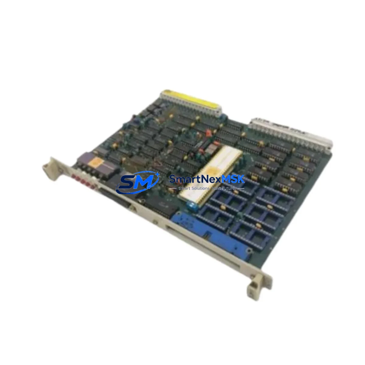
The ABB GJR2363900R1000 (88VT02B-E) is an original printed circuit board designed for ABB AC500 series programmable logic controllers and distributed control systems. For maintenance engineers managing continuous production lines, unplanned downtime caused by a failed PCB module can cascade into hours of lost output. Stocking a verified replacement of the GJR2363900R1000 is a proven strategy to compress mean time to repair (MTTR) and restore system availability without waiting on extended lead times.
This board is sourced as a genuine ABB spare, inspected prior to dispatch, and shipped with a 12-month warranty. Each unit undergoes functional verification before leaving the warehouse, ensuring that the replacement you receive is ready for immediate installation into your AC500 control cabinet. Whether you are executing a planned shutdown, responding to an emergency fault, or building a strategic spare parts inventory, the GJR2363900R1000 delivers the reliability your operation demands.
Spare Maintenance Table
| Parameter | Specification |
|---|---|
| Part Number | GJR2363900R1000 |
| Variant / Revision | 88VT02B-E |
| Brand | ABB |
| Compatible Series | ABB AC500 PLC / DCS |
| Module Type | Printed Circuit Board (PCB) |
| Origin | Germany (DE) |
| Weight | 550 g (approx.) |
| Installation | Direct board-level replacement; observe ESD precautions |
| Operating Environment | Industrial control cabinet; standard IEC 61131-2 conditions |
| Compatibility Verification | Cross-reference firmware revision and backplane slot assignment before installation |
| Maintenance Recommendation | Inspect connector pins, check for thermal stress marks, verify power rail voltages before and after swap |
| Warranty | 12 Months — covers manufacturing defects and functional failure under normal operating conditions |
| Pre-shipment Test | Functional verification performed on every unit prior to dispatch |
Maintenance Planning for Continuous Operation
When a GJR2363900R1000 board failure is identified during routine control cabinet inspection or fault diagnostics, experienced maintenance engineers know that the PCB rarely fails in isolation. A thorough site assessment should include the following components within the same AC500 rack and electrical circuit:
Begin with the AC500 CPU module (e.g., PM573 or PM583 series) to confirm that the processor is not generating persistent fault codes that indicate upstream power or communication issues. Check the 24 VDC power supply module feeding the rack — voltage sags or ripple can stress PCB components over time and accelerate board failure. Inspect the SM560 or equivalent digital I/O modules sharing the same backplane, as a shorted field device on an I/O channel can propagate damage to adjacent boards.
Review the communication interface module (such as a CM572-DP PROFIBUS module or CM589-PNIO PROFINET adapter) for error counters that may indicate intermittent signal loss preceding the board fault. Examine terminal blocks and field wiring at the I/O marshalling panel — loose terminations or corroded contacts are a common root cause of board-level stress. If the cabinet includes a signal isolator or barrier module between field instruments and the PLC I/O, verify isolation resistance and check for leakage current.
For systems with relay output modules adjacent to the GJR2363900R1000, inspect the relay output board for contact wear and coil resistance — inductive load switching can generate voltage spikes that degrade nearby PCBs. Check the backplane bus connector for oxidation or mechanical damage, as poor backplane contact is a frequent but overlooked cause of intermittent board faults. Finally, if the AC500 system interfaces with an HMI panel (such as an ABB CP600 series), verify that the HMI communication link is stable and that no watchdog timeouts are being logged, which could indicate a systemic communication fault rather than an isolated PCB failure.
Building a maintenance kit that includes the GJR2363900R1000 alongside a spare CPU module, a replacement power supply, and a set of I/O modules for the most critical channels is a best practice for facilities operating AC500-based systems in high-availability environments.
Site Replacement Workflow
Step 1 — Fault Isolation: Use the AC500 diagnostic software (Automation Builder or PS501 Control Builder) to read the active fault log. Confirm that the GJR2363900R1000 board is the source of the fault and not a downstream field device or communication error.
Step 2 — Safe Isolation: Follow your site’s lockout/tagout (LOTO) procedure. De-energize the control cabinet and discharge any residual voltage on the backplane power rails before handling the PCB.
Step 3 — ESD Protection: Use a grounded wrist strap and anti-static mat. The GJR2363900R1000 contains sensitive CMOS components that can be damaged by electrostatic discharge even when the cabinet is de-energized.
Step 4 — Board Removal and Inspection: Remove the faulty board and inspect the slot connector, adjacent modules, and backplane for signs of arcing, overheating, or contamination. Document findings for root cause analysis.
Step 5 — Replacement Installation: Insert the new GJR2363900R1000 into the correct backplane slot. Verify that the firmware revision of the replacement board is compatible with the CPU firmware version currently running on the AC500 system. If a firmware update is required, perform it before re-energizing.
Step 6 — Power-Up and Verification: Re-energize the cabinet and monitor the diagnostic LEDs on the replacement board. Confirm that the CPU recognizes the module and that no new fault codes are generated. Run a functional test of all I/O channels associated with the replaced board before returning the system to production.
This structured workflow minimizes the risk of repeat failures, reduces total downtime, and ensures that the replacement is fully validated before the system resumes operation. For aging AC500 installations, this replacement procedure also provides an opportunity to assess whether adjacent modules should be proactively replaced to extend overall system life.
Spare Parts Support FAQ
Q1: Is the GJR2363900R1000 a new original part or a refurbished unit?
All units supplied are original ABB spare parts. Each board is individually inspected and functionally tested before shipment. Refurbished or repaired boards are not supplied under this listing. The 12-month warranty applies from the date of delivery.
Q2: How do I verify compatibility with my specific AC500 system revision?
Cross-reference the part number GJR2363900R1000 and the revision code 88VT02B-E against your AC500 system’s hardware configuration report, which can be exported from Automation Builder. If you require compatibility confirmation before ordering, contact our technical team with your CPU part number and firmware version.
Q3: What is the typical lead time and how is the board packaged for shipment?
In-stock units are dispatched within 1–3 business days. The board is packaged in anti-static shielding bags, placed in foam-lined cartons, and shipped via tracked express courier to minimize transit risk. A test report is included with each shipment.
Q4: Can I return the board if it does not resolve the fault after installation?
Yes. If the GJR2363900R1000 does not resolve the identified fault and the board has not been physically damaged during installation, it may be returned within the warranty period. Contact our support team with the fault log and installation details. We will assist with root cause analysis and, if applicable, arrange a replacement or refund under the 12-month warranty terms.
© 2026 SMARTNEXMSK. All rights reserved.
Original Source: https://smartnexmsk.com
Contact: sales@smartnexmsk.com | +86 18259474341


