ABB GJR2365700R1010 Retrofit-Ready CPU for AC500 Systems: Compatible Modernization for Legacy Control Infrastructure
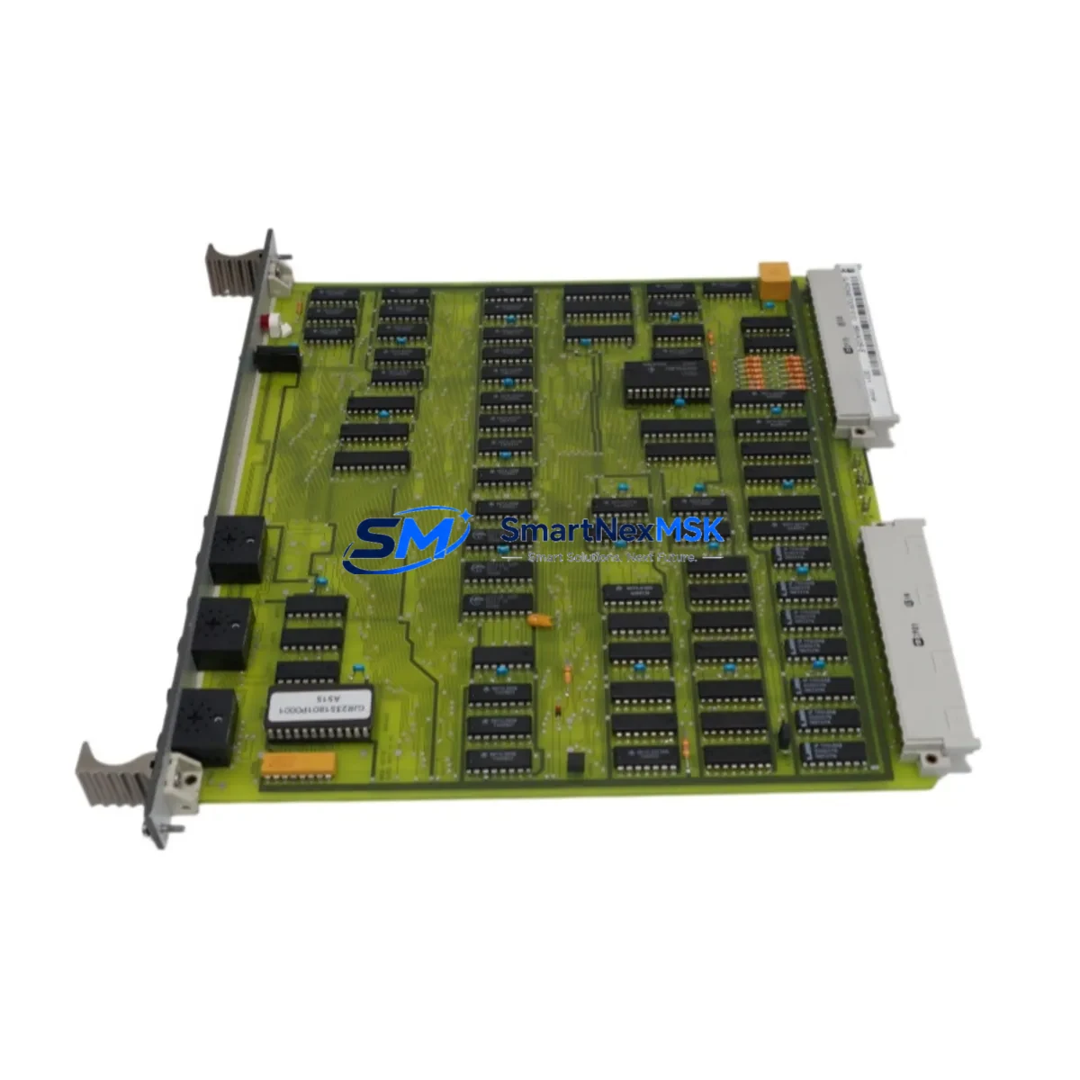
The ABB GJR2365700R1010 (88VA02A-E) is a central processing unit module designed for the ABB AC500 PLC platform — one of the most widely deployed programmable logic controller families in industrial automation. As legacy AC500 installations age and original spare parts become increasingly difficult to source, this retrofit-ready replacement module provides a reliable, specification-matched solution for engineers managing aging control systems, production line upgrades, and control cabinet modernization projects.
Whether you are replacing a failed CPU in an active production environment, upgrading a discontinued module in a legacy panel, or migrating an older AC500 rack to a more maintainable configuration, the GJR2365700R1010 is engineered to restore system functionality with minimal disruption to existing wiring, programming, and field instrumentation.
Upgrade Compatibility Table
| Parameter | Details |
|---|---|
| SKU / Part Number | GJR2365700R1010 / 88VA02A-E |
| Platform | ABB AC500 PLC Series |
| Module Type | CPU / Central Processing Unit |
| Backplane Interface | AC500 standard backplane bus (compatible with PM5xx rack) |
| Communication Ports | Ethernet (MODBUS TCP / IEC 61850 capable), Serial (CS31) |
| Installation Requirement | DIN rail or rack-mount; matches AC500 standard footprint |
| Replacement Compatibility | Direct replacement for discontinued 88VA02A-E variants |
| Program Compatibility | IEC 61131-3 compliant; supports Automation Builder project restore |
| Commissioning Note | Verify firmware version and memory card slot before power-on |
| Warranty | 12 months from date of shipment |
| Pre-Shipment Testing | Full functional test performed before dispatch |
Retrofit Planning for Existing Automation Systems
Successful retrofit of the GJR2365700R1010 into an existing AC500 installation requires systematic pre-replacement planning. Before removing the original CPU, engineers should document the current rack configuration, including the positions of all installed I/O modules such as the DC532 digital input module and DC522 digital output module, as well as any analog expansion cards like the AX522 analog I/O module. These modules communicate with the CPU over the AC500 internal backplane bus, and their slot addresses must be preserved in the replacement configuration.
Power supply capacity is a critical verification step. The AC500 PS501 power supply module must be confirmed to provide sufficient current for the full rack load, including the new CPU and all connected I/O. Undersized power supplies are a common cause of intermittent faults following CPU replacement. Check the total current draw against the PS501 datasheet before proceeding.
For installations using the CM572-DP PROFIBUS DP communication module or the CM589-PNIO PROFINET I/O coupler, communication parameters including station addresses, baud rates, and GSD/GSDML device descriptions must be re-verified after the CPU swap. The replacement CPU must be loaded with the same network configuration to avoid address conflicts on the fieldbus segment.
If the system includes an ABB CP600 HMI panel or a third-party operator interface connected via Ethernet or serial link, the HMI project should be backed up prior to the retrofit. Screen tags, variable bindings, and alarm configurations are typically unaffected by a CPU swap if the program variable structure is preserved, but communication driver settings should be re-confirmed after restart.
For systems using a TK501 programming cable or USB-to-serial adapter for local programming access, ensure the Automation Builder software version on the engineering workstation is compatible with the firmware on the replacement CPU. Firmware mismatches can prevent project upload or cause unexpected behavior during commissioning. In some cases, a firmware update via the SD memory card slot on the CPU front panel may be required before the project can be restored.
All replacement modules are pre-shipment tested under simulated load conditions and shipped with a 12-month warranty covering manufacturing defects and functional failures under normal operating conditions.
Downtime Control During System Migration
Minimizing unplanned downtime is the primary concern in any live-system CPU replacement. The recommended approach is to perform a full program backup from the existing CPU using Automation Builder before any hardware is disturbed. Save the project file, including all POU (Program Organization Unit) blocks, variable declarations, and network configuration, to a secure engineering workstation and a secondary backup location.
Where possible, schedule the physical swap during a planned maintenance window. Power down the rack in the correct sequence — field devices first, then I/O modules, then the CPU and power supply. Label all terminal connections on the TB521 terminal base or equivalent wiring carrier before disconnection. Photograph the wiring layout as an additional reference.
After installing the GJR2365700R1010, restore power to the rack and verify that the CPU enters RUN mode without fault LEDs. Download the backed-up project and perform a cold start. Monitor all I/O channels for correct signal mapping before releasing the system to production. For critical processes, a parallel test using a temporary bypass or shadow control loop can further reduce risk during the transition period.
With proper preparation, most AC500 CPU replacements can be completed within a single shift, preserving existing program logic, field wiring, and HMI screen configurations without modification.
Retrofit Support FAQ
Q: Is the GJR2365700R1010 a direct drop-in replacement for the original 88VA02A-E?
A: Yes. The GJR2365700R1010 is the part number for the 88VA02A-E CPU module. It is physically and electrically compatible with the AC500 rack and backplane. No hardware modifications are required for installation.
Q: Can I restore my existing Automation Builder project to this replacement CPU?
A: In most cases, yes. The project can be downloaded directly via Ethernet or the programming port. Verify that the firmware version on the replacement CPU matches or is compatible with the version used during original project development. A firmware update may be required in some cases.
Q: What wiring changes are needed during the CPU swap?
A: The GJR2365700R1010 uses the same terminal base and backplane connector as the original module. No rewiring of field terminals is required. Only the CPU module itself is replaced; all I/O wiring remains connected to the existing terminal bases and expansion modules.
Q: What does the 12-month warranty cover?
A: The warranty covers manufacturing defects and functional failures under normal industrial operating conditions for 12 months from the date of shipment. Each unit undergoes full functional pre-shipment testing. Warranty claims are supported by our technical team with fast replacement dispatch.
© 2026 SMARTNEXMSK. All rights reserved.
Original Source: https://smartnexmsk.com
Contact: sales@smartnexmsk.com | +86 18259474341


