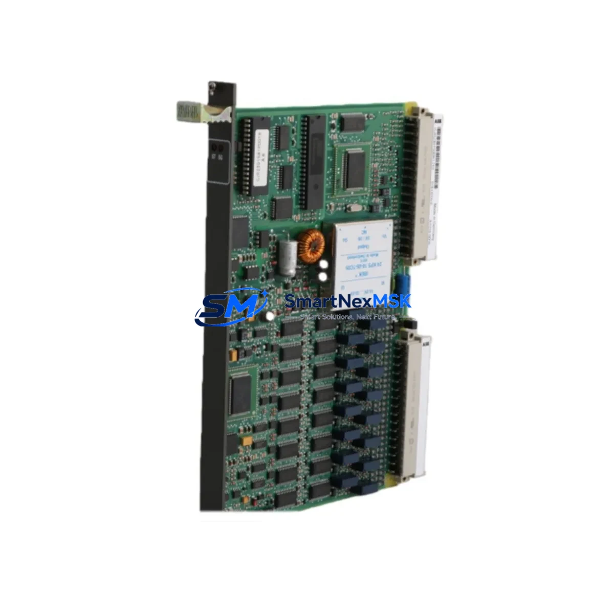
ABB GJR2391500R1210 81EU01H Retrofit-Ready Universal Input Module for AC500 Control Systems
The ABB GJR2391500R1210 (81EU01H) is a Universal Input Module designed for the ABB AC500 PLC platform — one of the most widely deployed modular programmable logic controller families in industrial automation. As legacy AC500 configurations age and original spare parts become increasingly difficult to source, this module serves as a verified retrofit-ready replacement for discontinued or end-of-life input modules within the same control architecture. Whether you are upgrading an aging control cabinet, restoring a production line after an unplanned failure, or executing a planned system modernization, the GJR2391500R1210 provides a reliable, specification-matched solution with minimal engineering rework.
This module supports multiple signal types across its universal input channels, making it suitable for mixed-signal environments where thermocouples, RTDs, voltage signals, and current loops must be handled within a single rack slot. Its compatibility with the AC500 backplane bus ensures seamless integration alongside other AC500 I/O modules, including digital input modules such as the DI581-S, digital output modules such as the DO581-S, and analog output modules such as the AO523. When combined with the AC500 CPU modules — including the PM573-ETH or PM591-ETH — the GJR2391500R1210 participates in the same program scan cycle without requiring changes to the existing PLC program structure, provided the module address and slot assignment are preserved during installation.
Upgrade Compatibility Table
| Parameter | Details |
|---|---|
| Compatible Platform | ABB AC500 PLC Series (S500 I/O) |
| Module Type | Universal Input Module (UI) |
| Backplane Interface | AC500 S500 I/O bus — direct slot replacement |
| Signal Compatibility | Thermocouple, RTD (Pt100/Pt1000), 0–10 V, 0/4–20 mA |
| Installation Requirement | DIN rail mount; standard AC500 terminal block wiring |
| Communication Compatibility | AC500 internal I/O bus; compatible with PROFIBUS DP, Modbus RTU, Ethernet/IP via CPU |
| Replacement Recommendation | Direct replacement for same-slot UI modules in AC500 racks; verify terminal assignment before wiring |
| Commissioning Focus | Module address confirmation, channel scaling parameters, signal type selection via Automation Builder |
| Warranty | 12-Month Warranty — covers manufacturing defects and functional failure under normal operating conditions |
Retrofit Planning for Existing Automation Systems
Successful retrofit of the GJR2391500R1210 into an existing AC500 installation requires a structured pre-installation review. Begin by documenting the current rack layout, including the slot positions of all installed modules. In a typical AC500 control cabinet, the CPU module — such as the PM573-ETH — occupies the leftmost slot of the CPU rack, with I/O modules extending to the right across the TB521 or TB541 terminal base units. The GJR2391500R1210 mounts onto a compatible terminal base, and the terminal base itself must be verified for compatibility with the universal input signal types in use at your site.
Before removing the existing module, photograph or document all field wiring connections at the terminal base. Universal input modules in AC500 systems typically handle signals from temperature sensors, pressure transmitters, and flow meters — each requiring specific channel configuration in the Automation Builder programming environment. After physical installation of the replacement module, open the Automation Builder project and confirm that the hardware configuration tree reflects the correct module type in the correct slot. If the original module was configured as a different variant, update the hardware configuration and perform a full download to the CPU.
For sites running PROFIBUS DP networks, verify that the DP coupler — such as the CI501-PNIO or CI502-PNIO — remains correctly addressed and that the GSD file associated with the AC500 I/O station has not been altered. In Modbus RTU environments, confirm that the communication module such as the CI504-PNIO or a dedicated serial communication interface retains its node address and baud rate settings. Where Ethernet-based communication is in use, the PM591-ETH CPU’s IP address and subnet configuration should be verified post-replacement to ensure uninterrupted SCADA or HMI connectivity.
Power budget verification is a critical step often overlooked during module replacement. The AC500 power supply module — such as the PS501-PROC or PS560-MC — must have sufficient residual capacity to support the GJR2391500R1210’s internal consumption alongside all other installed I/O modules. Consult the rack power budget calculation in the AC500 system manual and confirm that the total current draw does not exceed the rated output of the installed power supply. If the existing power supply is operating near its rated limit, consider upgrading to a higher-capacity unit as part of the retrofit scope.
For HMI integration, verify that the CP600 or CP620 operator panel screens referencing input channel values from the replaced module continue to display correctly after the module swap. Tag address mappings in the HMI project should be cross-checked against the updated PLC program to confirm that no symbolic address changes were introduced during the hardware configuration update.
Downtime Control During System Migration
Minimizing production downtime during a module replacement requires advance preparation and a disciplined execution sequence. Before scheduling the maintenance window, obtain the replacement GJR2391500R1210 module and verify its physical condition and firmware compatibility. Confirm with the site engineer that a current, tested backup of the PLC program exists in Automation Builder and that the backup has been validated against the live system within the past maintenance cycle.
During the maintenance window, follow a structured sequence: isolate field power to the affected input channels, remove field wiring from the terminal base (not the module itself, if the terminal base is retained), extract the faulty module from the terminal base, insert the replacement GJR2391500R1210, reconnect field wiring according to the documented terminal assignment, restore field power, and then perform a controlled CPU restart or hot-swap sequence as permitted by the AC500 firmware version in use. In AC500 systems that support hot-swap I/O replacement, the CPU may continue executing the control program during the module exchange, provided the slot configuration in the hardware tree matches the replacement module type.
After restoration, verify each input channel individually using the Automation Builder online monitoring view or the CP600 HMI diagnostic screen. Confirm that all process values are within expected ranges before releasing the system to automatic control. Document the replacement event in the site maintenance log, including the module serial number, installation date, and the name of the commissioning engineer. This documentation supports the 12-month warranty claim process if a defect is identified during the warranty period.
Retrofit Support FAQ
Q1: Is the GJR2391500R1210 a direct drop-in replacement for other ABB AC500 universal input modules?
A: In most cases, yes — provided the replacement module occupies the same slot on a compatible terminal base and the Automation Builder hardware configuration is updated to reflect the correct module type. Channel count, signal type support, and terminal base compatibility should be verified against the original module’s datasheet before installation. Our technical team can assist with compatibility confirmation prior to shipment.
Q2: What commissioning steps are required after installing the replacement module?
A: After physical installation, connect to the AC500 CPU using Automation Builder, update the hardware configuration if the module type differs from the original, perform a program download, and verify each input channel in online monitoring mode. Confirm signal scaling, engineering unit conversion, and alarm threshold settings match the original configuration. For temperature input channels, verify that the correct sensor type (thermocouple type or RTD class) is selected in the channel configuration dialog.
Q3: How is wiring compatibility verified before installation?
A: Compare the terminal assignment diagram of the GJR2391500R1210 with the existing field wiring documentation. Universal input modules in the AC500 S500 I/O family use standardized terminal base layouts, but signal type and channel grouping may vary between module variants. Confirm that the field cable screen connections, common terminals, and power supply terminals are correctly mapped before energizing the module.
Q4: What does the 12-month warranty cover, and how is a claim initiated?
A: The 12-month warranty covers manufacturing defects and functional failures under normal operating conditions, including signal measurement inaccuracy beyond published specifications, communication bus faults attributable to the module, and physical defects present at the time of delivery. To initiate a warranty claim, contact sales@smartnexmsk.com with the module serial number, purchase order reference, fault description, and site installation details. Replacement or repair will be arranged within the warranty terms.
© 2026 SMARTNEXMSK. All rights reserved.
Original Source: https://smartnexmsk.com
Contact: sales@smartnexmsk.com | +86 18259474341


