ABB GJR2391500R1210 Spare for AC500 Automation: Spare Replacement & Downtime Risk Control
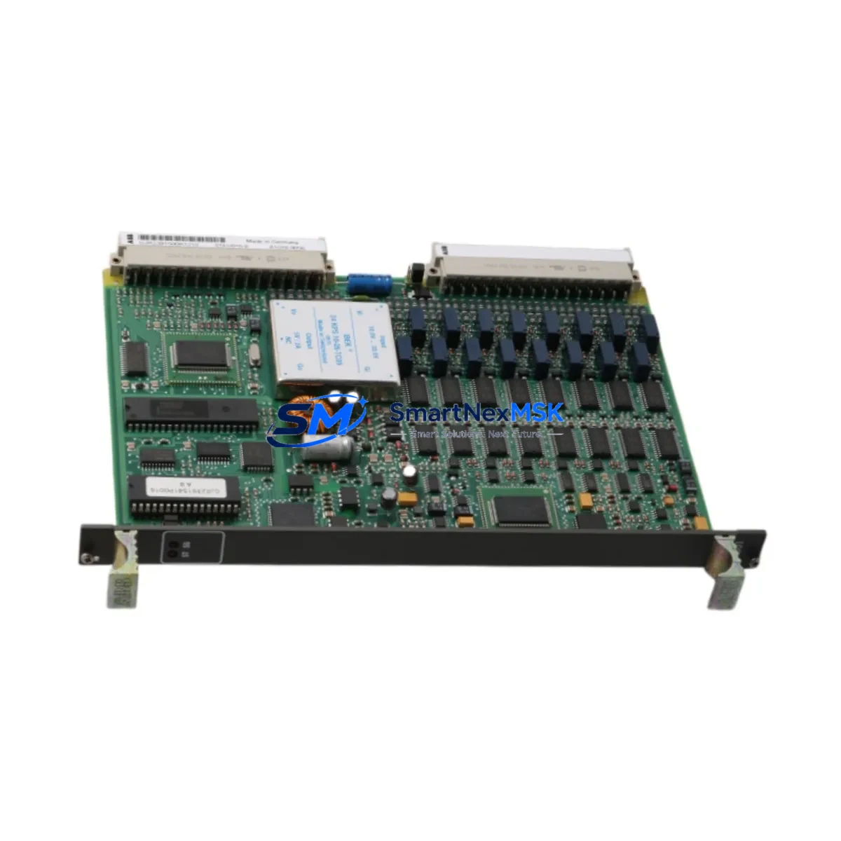
The ABB GJR2391500R1210 (also identified as 81EU01H-E) is an original digital input module designed for the ABB AC500 PLC platform — one of the most widely deployed programmable logic controller families in industrial automation, process control, and critical infrastructure applications. When this module fails or degrades, the consequences extend beyond a single I/O channel: the entire control loop dependent on that input signal is compromised, potentially triggering unplanned shutdowns, safety interlocks, or production losses that far exceed the cost of the spare part itself.
Sourcing a verified, original GJR2391500R1210 replacement is the fastest path to restoring system integrity. This spare is supplied as an original ABB component, fully tested prior to shipment, and backed by a 12-month warranty — giving maintenance engineers and procurement teams the confidence to stock it as a first-line replacement in their MRO inventory.
Spare Maintenance Table
| Parameter | Specification / Detail |
|---|---|
| Part Number | GJR2391500R1210 |
| Alternate ID | 81EU01H-E |
| Brand | ABB |
| Series | AC500 |
| Module Type | Digital Input Module |
| Origin | Germany (DE) |
| Compatibility | ABB AC500 PLC platform; compatible with standard AC500 backplane and CPU modules |
| Installation | DIN rail / AC500 backplane slot mounting; hot-swap capable per system configuration |
| Application Environment | Industrial automation, process control, MRO, panel upgrades, legacy system extension |
| Maintenance Recommendation | Inspect input wiring, terminal blocks, and field device signals during replacement; verify firmware compatibility with CPU module |
| Condition | Original, new |
| Pre-shipment Testing | Functional test performed before dispatch |
| Warranty | 12 months from date of shipment |
| Weight | 420 g |
Maintenance Planning for Continuous Operation
When a GJR2391500R1210 digital input module is flagged for replacement during a planned shutdown or emergency callout, experienced maintenance engineers treat the event as an opportunity to audit the surrounding control cabinet. The AC500 platform is a modular system, and the health of the digital input module is closely tied to the condition of adjacent components.
Begin by inspecting the AC500 CPU module (such as the PM573 or PM591 series) for firmware version compatibility with the replacement DI module. A firmware mismatch can cause the new module to be unrecognized or to report false diagnostics. Next, verify the AC500 power supply module (PS501 or PS502 series) output voltage — an under-voltage condition is a common root cause of intermittent digital input faults that are misdiagnosed as module failure.
Check the terminal blocks and field wiring connected to the DI module’s input channels. Corroded terminals, loose ferrules, or damaged cable insulation can cause recurring faults even after a module swap. If the system uses signal isolators between field sensors and the PLC input, inspect these for drift or failure — a degraded isolator will corrupt the input signal regardless of the module’s condition.
For cabinets with mixed I/O, also inspect the AC500 digital output modules (such as DO501 or DO502 series) and any installed analog input/output modules (AI523, AO523) sharing the same backplane. Backplane connector wear or contamination can affect multiple modules simultaneously. If the system includes communication modules (CM572-DP for PROFIBUS or CM589-PNIO for PROFINET), verify their status LEDs and bus termination — a communication fault can mask or mimic I/O module errors.
Where relay output modules (such as the DO531) are used in the same control loop, inspect relay contact wear and coil voltage. Relay degradation is a frequent companion fault in aging AC500 panels. Finally, if an HMI panel (such as an ABB CP600 series) is connected to the AC500 CPU, use it to review the diagnostic buffer for historical fault codes before clearing alarms — this log often reveals whether the DI module failure was sudden or progressive, informing your spare parts stocking strategy.
Maintaining a minimum stock of one GJR2391500R1210 per critical production line, alongside matched power supply and CPU spares, is a proven strategy for reducing mean time to repair (MTTR) in AC500-based systems.
Site Replacement Workflow
Step 1 — Isolate and document. Before removing the faulty module, record the slot address, I/O mapping, and any active diagnostic codes from the CPU or HMI. Take a photograph of the wiring and terminal labeling for reference during reinstallation.
Step 2 — Power down safely. De-energize the cabinet section feeding the DI module. Confirm with a multimeter that all input channels are de-energized before disconnecting field wiring. For systems with hot-swap capability, follow the AC500 system manual procedure to avoid bus errors.
Step 3 — Remove and inspect. Extract the GJR2391500R1210 from its backplane slot. Inspect the backplane connector for bent pins, corrosion, or debris. Clean with dry compressed air if necessary before inserting the replacement module.
Step 4 — Install the replacement. Insert the new GJR2391500R1210 into the same slot. Reconnect field wiring per the documented terminal layout. Verify that all ferrules are seated and terminal screws are torqued to specification.
Step 5 — Power up and verify. Restore power and observe the module status LED. A solid green LED indicates normal operation. Use the AC500 programming tool (Automation Builder or PS501 Control Builder) to confirm all input channels are reading correctly against known field device states.
Step 6 — Clear diagnostics and document. Clear the CPU diagnostic buffer after confirming normal operation. Update the maintenance log with the replacement date, module serial number, and any observations. This record supports warranty claims and future fault analysis.
This workflow applies equally to planned maintenance windows and emergency callouts, and is compatible with both legacy AC500 V1 and current AC500 V2 hardware generations — ensuring long-term system continuity without requiring platform migration.
Spare Parts Support FAQ
Q1: How long is the warranty on the GJR2391500R1210, and what does it cover?
This spare is covered by a 12-month warranty from the date of shipment. The warranty covers manufacturing defects and functional failures under normal operating conditions. Each unit is functionally tested before dispatch to verify correct operation prior to delivery.
Q2: Is this module compatible with both AC500 V1 and AC500 V2 hardware?
The GJR2391500R1210 is designed for the ABB AC500 platform. Compatibility with specific CPU generations (V1 vs V2) depends on the firmware version of the CPU module in your system. We recommend confirming the CPU firmware version against ABB’s compatibility matrix before installation. Our technical team can assist with compatibility verification upon request.
Q3: What is the recommended spare parts stocking strategy for AC500 DI modules?
For critical production lines, maintain a minimum of one GJR2391500R1210 per installed system. For facilities with multiple AC500 cabinets, a pooled inventory of 2–3 units is recommended to cover both planned maintenance and emergency replacement scenarios. Long-term supply availability is supported through our established sourcing channels.
Q4: How is the module tested and packaged before shipment?
Each GJR2391500R1210 undergoes functional testing to verify input channel operation, backplane communication, and LED diagnostics before packaging. Modules are shipped in anti-static packaging with protective foam inserts to prevent transit damage. Shipment tracking is provided for all orders.
© 2026 SMARTNEXMSK. All rights reserved.
Original Source: https://smartnexmsk.com
Contact: sales@smartnexmsk.com | +86 18259474341


