ABB GJR2392700R1210 Retrofit-Ready CPU for AC500 Control Systems: Compatible Modernization & Smooth Legacy Upgrade
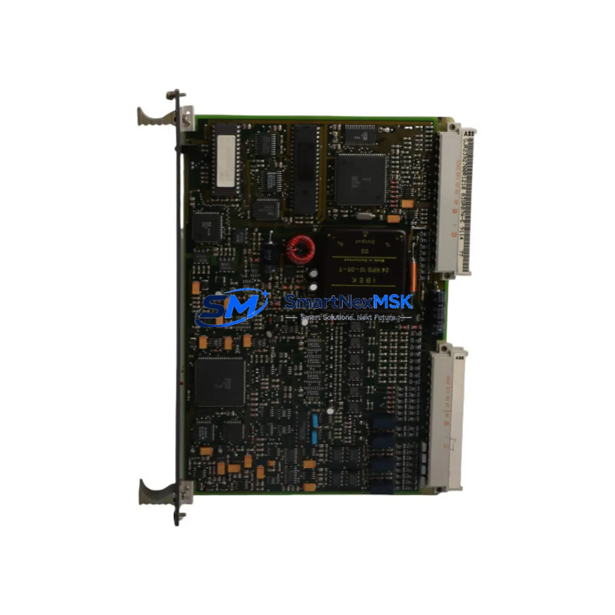
The ABB GJR2392700R1210 (also referenced as 83SR07A-E) is a central processing unit module designed for the ABB AC500 PLC series — one of the most widely deployed programmable logic controller platforms in industrial automation, process control, and power distribution applications worldwide. As legacy AC500 installations age and original modules reach end-of-life or become discontinued, the GJR2392700R1210 serves as a verified retrofit-ready replacement that preserves existing program logic, field wiring, and communication architecture while restoring full system reliability.
Whether you are managing a planned control system upgrade, responding to an unplanned module failure, or executing a phased modernization of an aging production line, the GJR2392700R1210 is engineered to minimize engineering rework and reduce total downtime. This module is sourced from authorized supply channels, undergoes pre-shipment functional testing, and is backed by a 12-month warranty.
Upgrade Compatibility Table
| Parameter | Details |
|---|---|
| SKU / Part Number | GJR2392700R1210 / 83SR07A-E |
| Compatible Platform | ABB AC500 PLC Series (PM5xx, PM5xx-ETH variants) |
| Backplane / Rack Interface | AC500 standard backplane; compatible with TB5xx terminal base units |
| Communication Protocols | Modbus RTU, Modbus TCP/IP, PROFIBUS DP, CANopen (via CM modules) |
| Installation Requirement | Direct module swap on TB5xx terminal base; no backplane modification required |
| Power Supply Compatibility | 24 VDC system bus; verify PS5xx power supply capacity before installation |
| Replacement Recommendation | Suitable direct replacement for discontinued AC500 CPU modules of equivalent generation |
| Commissioning Note | Restore program via Automation Builder; verify I/O module addresses and CM communication parameters |
| Warranty | 12 months from date of shipment |
| Origin | Germany (DE) |
| Pre-Shipment Testing | Functional power-on and communication link verification performed before dispatch |
Retrofit Planning for Existing Automation Systems
Successful integration of the GJR2392700R1210 into an existing AC500 installation requires a structured pre-replacement assessment. Begin by documenting the current system configuration: record the installed TB511-ETH terminal base or equivalent TB5xx unit, confirm the firmware revision of the outgoing CPU, and export the full project from ABB Automation Builder before any hardware is disturbed. This backup is your primary recovery asset.
Next, audit the power budget. The PS501 or PS502 power supply module feeding the rack must have sufficient headroom to support the replacement CPU alongside all installed I/O modules — including any DC532 digital I/O modules, AX522 analog I/O modules, or specialty function modules occupying the same rack. Overloaded power supplies are a common and preventable cause of post-retrofit instability.
For systems using fieldbus communication, verify that the CM572-DP PROFIBUS DP communication module or CM589-PNIO PROFINET module configuration parameters — including station addresses, baud rates, and GSD/GSDML device descriptions — are documented and backed up. These settings do not automatically transfer to a replacement CPU and must be manually restored or re-imported during commissioning. Similarly, if the system uses CANopen via a CM582-CN module, node IDs and network timing parameters must be re-verified after the swap.
Terminal wiring on the TB5xx base is fixed and does not require disconnection during a CPU module swap — a significant advantage that reduces retrofit time and eliminates rewiring errors. However, confirm that the field I/O wiring documentation is current and that any DA501 analog signal conditioners or external relay interface modules in the control cabinet are correctly mapped in the restored program.
If the installation includes an ABB CP600 HMI panel or a third-party SCADA system communicating via Modbus TCP/IP or OPC, verify that the IP address assignment and communication driver configuration on the HMI side remain consistent with the replacement CPU’s network settings. Screen tag bindings and alarm setpoints should be validated against the restored PLC program before returning the system to automatic mode.
Finally, confirm module slot addressing in the Automation Builder hardware configuration matches the physical rack layout. Mismatched slot assignments between the software configuration and the physical installation are a frequent source of I/O faults following a CPU replacement and must be resolved before the first program download.
Downtime Control During System Migration
Minimizing production downtime during a CPU module replacement on an AC500 system is achievable with disciplined pre-work. The most effective strategy is to complete all software preparation — program backup, hardware configuration export, and communication parameter documentation — during normal production hours, so that the physical swap window is limited to the actual hardware exchange and commissioning steps only.
Before initiating the swap, place the system in a safe state: confirm that all field outputs are de-energized or held in a safe position by the process, and that any interlocked systems — including upstream or downstream PLCs communicating via PROFIBUS or Modbus — are aware of the planned interruption. Coordinate with operators to ensure that HMI alarm acknowledgment procedures are in place for the transition period.
The physical module exchange on a TB5xx terminal base is a tool-free operation. Once the replacement GJR2392700R1210 is seated, connect a programming laptop running Automation Builder via the onboard Ethernet port and download the previously backed-up project. Verify that the CPU transitions to RUN mode without I/O faults, confirm communication link status on all CM modules, and perform a structured I/O check — cycling each output and verifying each input — before releasing the system to automatic operation.
For critical processes where even brief interruptions are costly, consider staging the replacement CPU on a bench with a duplicate hardware configuration for pre-commissioning and program verification before the planned maintenance window. This approach compresses the live swap to under 30 minutes in most AC500 installations and protects the original program logic from being altered under time pressure.
Retrofit Support FAQ
Q1: Is the GJR2392700R1210 a direct drop-in replacement for my existing AC500 CPU module?
In most AC500 installations using a compatible TB5xx terminal base, the GJR2392700R1210 is a direct physical replacement. Confirm that the terminal base model and firmware generation are compatible before ordering. Our technical team can assist with compatibility verification based on your existing part number and system configuration.
Q2: Do I need to re-wire the terminal base when replacing the CPU module?
No. The AC500 architecture separates the CPU module from the field wiring via the TB5xx terminal base. The CPU module plugs into the terminal base without disturbing any field wiring connections, significantly reducing replacement time and eliminating rewiring risk.
Q3: How do I restore my PLC program after installing the replacement module?
Use ABB Automation Builder to download the previously exported project to the replacement CPU via the onboard Ethernet port. Ensure the hardware configuration in the project matches the physical rack layout, including all I/O module slot assignments and CM communication module parameters. A full I/O functional test is recommended before returning to automatic operation.
Q4: What does the 12-month warranty cover, and what pre-shipment testing is performed?
Every GJR2392700R1210 unit undergoes functional power-on testing and communication link verification before dispatch. The 12-month warranty covers manufacturing defects and functional failures under normal operating conditions. Units are shipped with protective packaging to prevent ESD and transit damage. Contact sales@smartnexmsk.com for warranty claims or technical support.
© 2026 SMARTNEXMSK. All rights reserved.
Original Source: https://smartnexmsk.com
Contact: sales@smartnexmsk.com | +86 18259474341


