ABB GJR5251400R0202 Maintenance-Ready Spare for AC31 Automation
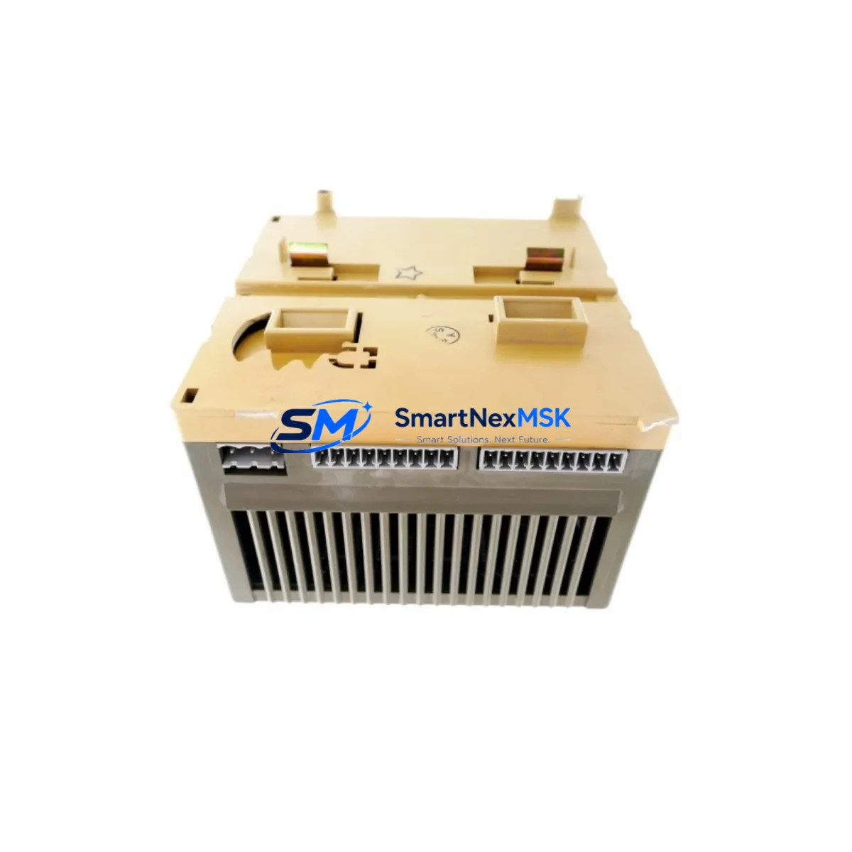
The ABB GJR5251400R0202 (07DC91) is an original digital I/O module designed for the Advant Controller 31 (AC31) series — one of ABB’s most widely deployed compact PLC platforms in process automation, machine control, and building management applications. As a maintenance-ready spare, this module is sourced, inspected, and dispatched to support rapid fault recovery and planned maintenance cycles in facilities where AC31 controllers remain the backbone of critical operations.
For maintenance engineers managing aging AC31 installations, the GJR5251400R0202 represents a direct, drop-in replacement that eliminates the need for costly system redesigns or controller migrations. Its original ABB manufacture ensures full electrical and firmware compatibility with the AC31 backplane, I/O bus, and associated programming environment. Every unit is function-tested prior to shipment and covered by a 12-month warranty, giving procurement teams the confidence to stock this module as a long-term spare.
Spare Maintenance Table
| Parameter | Specification |
|---|---|
| Part Number | GJR5251400R0202 |
| Alternate Reference | 07DC91 |
| Brand / Manufacturer | ABB (Original) |
| Series / Platform | Advant Controller 31 (AC31) |
| Module Type | Digital I/O Module |
| Country of Origin | Germany (DE) |
| Compatibility | AC31 backplane, 07KT98, 07KT97, 07KT94 CPU modules |
| Installation | DIN-rail mounted, plug-in backplane connector |
| Application Environment | Industrial automation, process control, HVAC, machine control |
| Operating Temperature | 0 °C to +55 °C (standard industrial range) |
| Maintenance Recommendation | Inspect connector pins, verify I/O bus integrity, confirm firmware revision before installation |
| Pre-shipment Testing | Full functional test performed on each unit |
| Warranty | 12 Months |
| Condition | Original / Genuine ABB |
Maintenance Planning for Continuous Operation
When a GJR5251400R0202 digital I/O module fails or is flagged during a scheduled inspection, the fault rarely exists in isolation. Experienced maintenance engineers know that a single I/O module fault can be symptomatic of broader issues within the control cabinet. Before returning the system to service, a thorough inspection of the surrounding components is essential.
Start with the AC31 power supply module — typically a 07AC91 or equivalent — to confirm that the 24 VDC bus voltage is stable and within tolerance. Voltage sags or ripple on the backplane supply are a common root cause of intermittent I/O faults. Next, inspect the backplane bus connector and the module’s edge connector for oxidation, bent pins, or contamination, particularly in environments with high humidity or airborne particulates.
The 07KT98 or 07KT97 CPU module should be checked for active fault codes and diagnostic logs. If the CPU has logged repeated I/O bus errors prior to the module failure, the backplane itself may require replacement. Alongside the CPU, verify the status of any installed communication modules — such as PROFIBUS DP or CS31 bus couplers — since a failed I/O module can disrupt bus communication and trigger cascading alarms across the network.
Field wiring connected to the I/O module’s terminal block should be inspected for loose terminations, insulation breakdown, or incorrect polarity. It is good practice to also test the associated 24 VDC field power fuses and any surge protection devices on the input/output lines. In systems with inductive loads, check whether freewheeling diodes or RC snubbers are intact on output channels, as their failure can cause voltage spikes that damage I/O modules over time.
For facilities running mixed AC31 and newer S800 I/O or AC500 PLC hardware in the same control room, this is also an appropriate time to audit the signal isolators and loop-powered transmitters feeding the AC31 inputs, ensuring that signal levels remain within the module’s rated input range. If the system includes relay output modules such as the 07CR41 or similar, inspect contact wear and coil resistance as part of the same maintenance event.
Stocking the GJR5251400R0202 alongside complementary spares — including the AC31 CPU module, power supply, PROFIBUS coupler, and a set of terminal block assemblies — forms the foundation of a resilient spare parts strategy for any facility dependent on AC31-based automation.
Site Replacement Workflow
Step 1 — Isolate and de-energize: Follow your site’s lockout/tagout (LOTO) procedure. Confirm that the AC31 rack is fully de-energized before removing the faulty GJR5251400R0202 module. Note the slot position and any DIP switch or jumper settings on the existing module before extraction.
Step 2 — Document and compare: Record the firmware label and hardware revision on the outgoing module. Compare against the replacement unit to confirm revision compatibility. For most AC31 installations, the GJR5251400R0202 is revision-agnostic at the hardware level, but it is good practice to verify with your site’s engineering documentation.
Step 3 — Install and secure: Insert the replacement module into the correct backplane slot, ensuring the bus connector is fully seated. Secure the module latch. Reconnect field wiring to the terminal block, verifying each wire against the I/O assignment list.
Step 4 — Power-up and verify: Re-energize the rack and observe the module’s LED status indicators. A healthy module should display a steady RUN or OK indicator within the AC31 CPU’s diagnostic cycle. Use the AC31 programming tool (Automation Builder or 907 PC) to confirm that all I/O channels are reporting correctly and that no bus fault codes are active.
Step 5 — Return to service: Log the replacement in your maintenance management system (CMMS), update the spare parts inventory, and reorder a replacement unit to restore your buffer stock. Downtime for a prepared team with a pre-tested spare is typically under 30 minutes.
Spare Parts Support FAQ
Q: Is the GJR5251400R0202 still available as a new original part?
A: ABB has progressively phased out AC31 series components as the platform approaches end-of-life. However, we maintain a dedicated inventory of original, unused GJR5251400R0202 modules sourced directly from authorized channels. Each unit is individually tested and shipped with a 12-month warranty, ensuring you receive a fully functional spare regardless of the production date.
Q: How do I verify compatibility with my existing AC31 system before ordering?
A: The GJR5251400R0202 (07DC91) is compatible with all standard AC31 backplane configurations using 07KT94, 07KT97, and 07KT98 CPU modules. If you are unsure of your system’s exact configuration, please share your rack layout or CPU part number with our technical team at sales@smartnexmsk.com and we will confirm compatibility before shipment.
Q: What does the 12-month warranty cover, and what is the returns process?
A: Our 12-month warranty covers all functional defects identified under normal operating conditions. If a module fails within the warranty period, we will arrange a replacement or full refund. Each unit is tested prior to dispatch; a test report is available on request. To initiate a warranty claim, contact sales@smartnexmsk.com with your order reference and a description of the fault.
Q: Can you supply multiple units for a planned maintenance stock program?
A: Yes. We support bulk procurement for maintenance stock programs, offering consistent pricing and priority allocation for repeat customers. For facilities managing multiple AC31 installations, we recommend holding a minimum of two GJR5251400R0202 modules in your on-site spare parts store to cover both emergency replacement and planned overhaul cycles. Contact us to discuss volume pricing and scheduled delivery arrangements.
© 2026 SMARTNEXMSK. All rights reserved.
Original Source: https://smartnexmsk.com
Contact: sales@smartnexmsk.com | +86 18259474341


