ABB HESG447440R0001 Maintenance-Ready Spare AC500 DCS: Spare Replacement & Industrial Downtime Risk Control
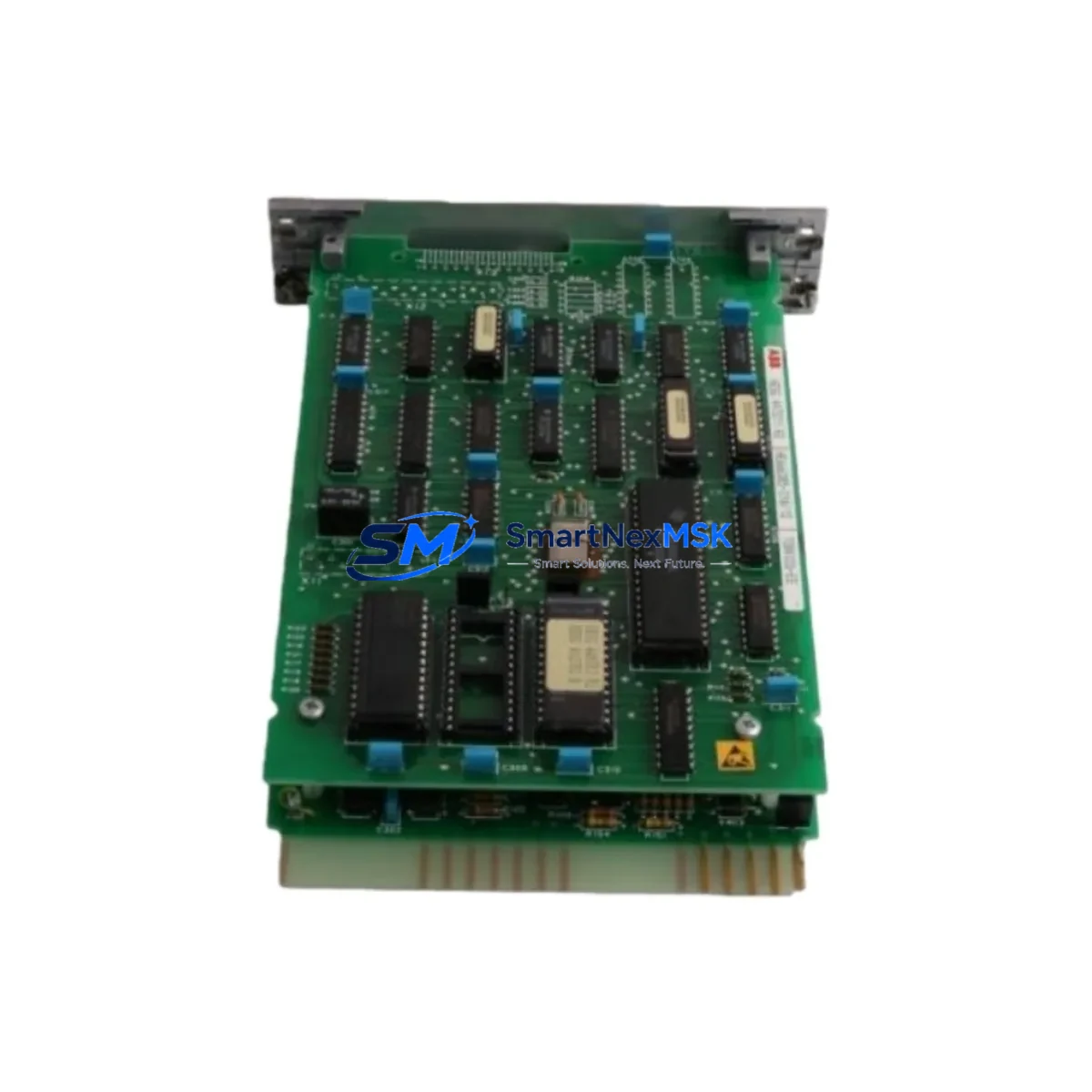
The ABB HESG447440R0001, also referenced as 70BK03C-E, is an original Bus Coupling Module designed for ABB’s AC500 Distributed Control System (DCS) platform. In industrial automation environments — from process plants and power utilities to manufacturing lines — this module serves as a critical communication bridge between the DCS backplane and field I/O networks. When this component fails or degrades, the consequences extend beyond a single loop: entire control segments can go offline, triggering unplanned shutdowns and costly production losses.
Sourced directly from ABB’s industrial supply chain and verified against original factory specifications, the HESG447440R0001 offered here is a genuine spare part — not a remanufactured substitute. Each unit undergoes functional testing prior to shipment, and is backed by a 12-month warranty covering manufacturing defects and operational failures under normal service conditions. For maintenance engineers managing aging AC500 DCS installations, having a verified replacement on the shelf is the single most effective strategy for minimizing mean time to repair (MTTR).
Spare Maintenance Table
| Parameter | Specification |
|---|---|
| Part Number | HESG447440R0001 |
| Alternate Reference | 70BK03C-E |
| Manufacturer | ABB |
| Country of Origin | Germany (DE) |
| Series / Platform | AC500 DCS |
| Module Type | Bus Coupling Module |
| Compatibility | ABB AC500 DCS backplane and I/O bus architecture |
| Installation | DIN rail / backplane slot mounting per AC500 system layout |
| Operating Environment | Industrial control cabinet; standard IEC 61131-2 conditions |
| Weight | 220 g |
| Condition | Original, factory-tested |
| Warranty | 12 months from shipment date |
| Pre-shipment Test | Functional verification performed on every unit |
| Maintenance Recommendation | Inspect bus connectors and backplane contacts every 12–18 months; replace on first sign of communication fault or CRC error escalation |
Maintenance Planning for Continuous Operation
Replacing the HESG447440R0001 Bus Coupling Module is rarely an isolated task. In a well-structured AC500 DCS control cabinet, the bus coupling module sits at the intersection of power distribution, I/O communication, and system diagnostics. A thorough maintenance plan should treat this replacement as a trigger for a broader cabinet inspection.
Begin with the 24 VDC power supply module feeding the AC500 rack — verify output voltage stability and ripple under load, as degraded power quality is a leading cause of premature bus module failure. Next, inspect the AC500 CPU module (such as the PM573 or PM583 series) for firmware currency and communication health logs; a failing bus coupler often generates diagnostic alarms that are first visible at the CPU level.
Check all digital input (DI) and digital output (DO) I/O modules installed in the same rack segment. Bus coupling faults can cause I/O modules to drop off scan, producing ghost faults in the control logic. Similarly, inspect analog input (AI) modules for signal drift that may have been masked by intermittent bus errors during the fault period.
Review the terminal blocks and field wiring connectors on the I/O side — vibration and thermal cycling can loosen connections that stress the bus coupler’s communication integrity. If the cabinet includes relay output modules or solid-state relay (SSR) interfaces, verify coil voltage and contact resistance, as these components share the same power rail and can introduce noise that degrades bus signal quality.
For systems with PROFIBUS DP or Modbus RTU communication modules in the same rack, confirm that bus termination resistors are correctly installed and that cable shielding is intact — a common oversight during emergency replacements. If a signal isolator or galvanic separator is present in the I/O loop, test isolation resistance to confirm it has not been compromised by the same fault event that damaged the bus coupler.
Finally, if the installation includes an ABB CP600 or CP400 series HMI panel communicating with the AC500 CPU, verify that the HMI communication link re-establishes cleanly after the bus coupler replacement and that all process variable displays return to expected values. Document the replacement in the site maintenance log and update the spare parts inventory to reflect the consumed unit — and order a replacement spare to restore buffer stock.
Site Replacement Workflow
Step 1 — Preparation: Obtain the HESG447440R0001 replacement unit and confirm the part number and revision against the installed module label. Download the current AC500 DCS project backup from the CPU before beginning any hardware work.
Step 2 — Safe Isolation: Follow site LOTO (Lockout/Tagout) procedures. De-energize the affected rack segment. Do not assume the bus coupler can be hot-swapped without confirming the system’s hot-swap capability for this specific module generation.
Step 3 — Module Removal: Disconnect the bus connector and any field wiring harnesses. Note the slot position and any DIP switch or jumper settings on the outgoing module before removal — photograph if necessary.
Step 4 — Installation: Seat the HESG447440R0001 firmly into the backplane slot. Reconnect bus connectors and field wiring. Verify that any configuration switches match the removed module’s settings.
Step 5 — Power-Up and Verification: Re-energize the rack. Observe the module’s status LEDs — a solid green RUN indicator confirms successful bus initialization. Check the CPU diagnostic buffer for any residual fault codes and clear confirmed faults. Verify all I/O modules in the segment return to active scan status.
Step 6 — Functional Test: Exercise representative I/O points from the HMI or engineering workstation to confirm end-to-end signal integrity. Log the replacement date, module serial number, and test results in the site maintenance record.
This workflow is applicable whether replacing a failed module in an emergency shutdown scenario or performing a planned swap during a scheduled maintenance window. The HESG447440R0001’s compatibility with the AC500 DCS architecture ensures no firmware reconfiguration is required in standard installations, significantly reducing restoration time compared to cross-brand substitutions.
Spare Parts Support FAQ
Q1: What is the expected service life of the HESG447440R0001, and when should I proactively replace it?
ABB AC500 DCS bus coupling modules are designed for long-term industrial service, typically 10–15 years under normal operating conditions. Proactive replacement is recommended when the module’s diagnostic counters show increasing CRC error rates, when the system is approaching end-of-support for the installed firmware generation, or as part of a planned lifecycle refresh for control systems older than 10 years. Maintaining one spare unit per installed rack segment is a widely adopted best practice in process industries.
Q2: How do I verify compatibility before installation?
Confirm the part number HESG447440R0001 (alternate: 70BK03C-E) matches the label on the installed module. Cross-reference the AC500 DCS system hardware manual for your specific CPU generation to confirm bus coupler compatibility. If your installation uses a mixed-generation rack, contact our technical team with your CPU part number for a compatibility confirmation before ordering.
Q3: What does the 12-month warranty cover, and what is the claims process?
The 12-month warranty covers manufacturing defects and functional failures under normal industrial operating conditions from the date of shipment. It does not cover damage resulting from incorrect installation, overvoltage events, or physical mishandling. To initiate a warranty claim, contact sales@smartnexmsk.com with your order number, a description of the fault symptom, and photographic evidence of the module condition. Replacement or refund will be processed within 5 business days of claim verification.
Q4: Can you support long-term or repeat supply for this part number?
Yes. SMARTNEXMSK maintains ongoing sourcing relationships for ABB AC500 DCS spare parts, including the HESG447440R0001. For facilities managing multiple AC500 installations or planning a multi-year maintenance contract, we can provide volume pricing, reserved stock agreements, and scheduled delivery programs. Contact us at sales@smartnexmsk.com or +86 18259474341 to discuss your long-term supply requirements.
© 2026 SMARTNEXMSK. All rights reserved.
Original Source: https://smartnexmsk.com
Contact: sales@smartnexmsk.com | +86 18259474341


