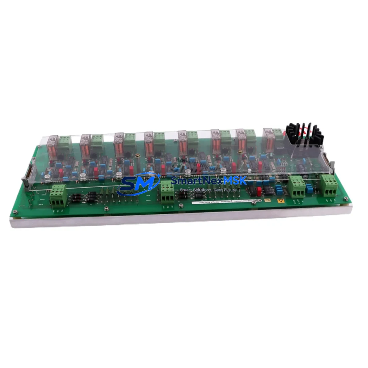
ABB HIEE200072R0002 Retrofit-Ready Power Supply for AC800M Control Systems
The ABB HIEE200072R0002 (USB030AE02) is a redundant power supply module engineered for seamless integration into ABB AC800M Distributed Control System (DCS) architectures. As legacy power supply units reach end-of-life or become unavailable through standard distribution channels, this module serves as the authoritative drop-in replacement — preserving existing backplane wiring, terminal assignments, and system redundancy logic without requiring controller reprogramming or cabinet redesign.
Industrial facilities operating AC800M-based control systems — including process plants, power generation units, and continuous manufacturing lines — frequently encounter the challenge of sourcing discontinued spare parts under time pressure. The HIEE200072R0002 addresses this directly: it maintains full electrical and mechanical compatibility with the PM865, PM866, and PM891 controller modules mounted on the same S800 I/O backplane, ensuring that power distribution to field I/O modules, communication interfaces, and redundant controller pairs remains uninterrupted during the swap procedure.
When planning a retrofit or emergency replacement using this module, engineers should verify the following before installation: incoming AC supply voltage range (typically 100–240 VAC, 50/60 Hz), terminal block torque specifications on the existing cabinet wiring, backplane slot assignment and module address configuration in the AC800M engineering tool (Control Builder M), and whether the redundant power supply pair is configured for hot-standby or load-sharing mode. Incorrect power capacity assumptions during a multi-module upgrade — particularly when adding CI854 PROFIBUS communication modules or AI810 / AO810 analog I/O modules to an existing rack — can cause nuisance trips or under-voltage faults that interrupt production.
Upgrade Compatibility Table
| Parameter | Detail |
|---|---|
| Part Number | HIEE200072R0002 / USB030AE02 |
| Brand | ABB |
| Compatible Series | AC800M (PM865, PM866, PM891) |
| Backplane Interface | S800 I/O Backplane — direct slot replacement |
| Redundancy Mode | Hot-standby redundant power supply pair |
| Communication Compatibility | PROFIBUS DP (CI854), FOUNDATION Fieldbus (CI873), Ethernet (CI873A) |
| Replaces / Supersedes | HIEE200072R0001, USB030AE01 (earlier hardware revision) |
| Installation Requirement | No firmware update required; plug-and-play on existing backplane |
| Commissioning Tool | ABB Control Builder M (CBM) — no address reassignment needed |
| Warranty | 12 Months — covers manufacturing defects and functional failure |
| Origin | Germany |
| Pre-shipment Test | Full functional burn-in and output voltage verification |
Retrofit Planning for Existing Automation Systems
A successful AC800M power supply retrofit begins well before the module arrives on-site. The engineering team should pull the existing cabinet drawings to confirm the terminal block layout used by the outgoing unit — particularly whether the installation uses a TB820V2 terminal block or a direct backplane mount. In systems where the CI854 PROFIBUS DP communication module is active, the power budget across the backplane must be recalculated to account for any additional AI810 analog input modules or DI810 digital input modules added during the upgrade window.
For plants running mixed I/O architectures — combining S800 I/O with legacy S100 or S200 I/O via an S800 I/O to S100 adapter — the power supply replacement must be coordinated with a review of the CI853 Modulebus Modem or CI801 PROFIBUS interface to ensure that fieldbus segment loading remains within specification. HMI screens built on ABB 800xA or linked via OPC DA/UA to third-party SCADA systems should be validated post-swap to confirm that the power module status tags (redundancy state, fault relay output) are correctly mapped and alarming as expected.
Where the retrofit scope extends to replacing the PM865 or PM866 controller module alongside the power supply, engineers should export and archive the current application program from Control Builder M before any hardware is removed. The SD card or compact flash memory holding the controller firmware and application image should be transferred to the replacement unit only after confirming hardware revision compatibility. Programming cables such as the TK212A USB-to-serial adapter may be required for initial controller communication if the Ethernet port is not yet configured.
Downtime Control During System Migration
Minimizing unplanned downtime during a power supply replacement on a live AC800M system requires a structured hot-swap procedure. Because the HIEE200072R0002 operates in a redundant pair, the failed or degraded unit can typically be removed while the standby unit maintains full power to the backplane — provided the redundancy configuration in Control Builder M is set to automatic switchover. Before initiating the swap, the control room operator should acknowledge any active power supply fault alarms and confirm that the standby unit is in a healthy state via the 800xA System Status display or the local LED indicators on the module faceplate.
The replacement module should be pre-inspected and bench-tested for correct output voltage before being brought to the cabinet. Once inserted into the backplane slot, the system will automatically detect the new module and restore the redundant pair status — typically within 30 seconds — without interrupting the running application program, field I/O scanning, or PROFIBUS communication cycles. Post-installation, the engineer should verify that the fault relay output contact has reset, that both power supply LEDs indicate normal operation, and that no new alarms have appeared in the 800xA alarm list. A full system log review covering the 15-minute window around the swap is recommended before returning the loop to automatic control.
Retrofit Support FAQ
Q1: Is the HIEE200072R0002 a direct replacement for the HIEE200072R0001?
Yes. The R0002 hardware revision is the current production version and is fully backward compatible with the R0001 in all AC800M backplane configurations. No wiring changes or software modifications are required. The module address and redundancy pairing are retained automatically upon insertion.
Q2: What commissioning steps are required after installation?
For a like-for-like replacement in a redundant pair, no Control Builder M project download is required. The engineer should confirm LED status (green RUN, no FAULT), verify output voltage at the backplane test points, and check the 800xA System Status view to confirm the redundancy pair is re-established. If the module is being installed in a new slot or replacing a single (non-redundant) unit, a CBM hardware configuration update may be needed.
Q3: How is terminal wiring compatibility confirmed before installation?
Refer to the existing cabinet wiring diagram for the outgoing unit. The HIEE200072R0002 uses the same terminal block footprint and pin assignment as previous revisions. If the installation uses a TB820V2 terminal block, the field wiring can remain connected during the module swap. Torque all terminals to the specification listed in the ABB AC800M Hardware Installation and Maintenance manual (3BSE041434).
Q4: What does the 12-month warranty cover, and what is the return process?
The 12-month warranty covers all manufacturing defects and functional failures under normal operating conditions. Each unit undergoes a full functional burn-in and output voltage verification test prior to shipment. In the event of a warranty claim, contact sales@smartnexmsk.com with the order reference and a description of the fault. A replacement unit will be dispatched or a repair assessment initiated within 3 business days.
© 2026 SMARTNEXMSK. All rights reserved.
Original Source: https://smartnexmsk.com
Contact: sales@smartnexmsk.com | +86 18259474341


