ABB ICSE08B5 FPR3346501R1012 Retrofit-Ready Relay Output for MOD 300 Control Systems
The ABB ICSE08B5 (alternate part number FPR3346501R1012) is an 8-channel relay output module engineered for the Advant MOD 300 Distributed Control System platform. As legacy MOD 300 installations approach end-of-support milestones, plant engineers and system integrators increasingly rely on verified replacement stock to sustain production continuity without committing to a full platform migration. This module provides a direct, drop-in upgrade path that preserves existing wiring harnesses, backplane slot assignments, and control logic — dramatically reducing retrofit risk and unplanned downtime.
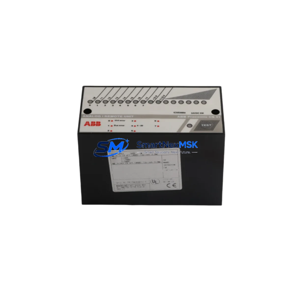
The ICSE08B5 interfaces directly with the MOD 300 S100 I/O bus backplane, occupying a standard single-width slot. Each of its eight relay channels supports dry-contact switching for discrete output control of field devices including solenoid valves, motor starters, alarm annunciators, and contactor coils. The module’s relay contacts are rated for both AC and DC loads, making it suitable for mixed-voltage control cabinets common in petrochemical, pulp-and-paper, and power generation facilities.
When planning a retrofit around the ICSE08B5, engineers should verify the power budget of the existing DSBC 176 or DSBC 110 bus connection unit, as adding or replacing relay output modules may affect the 24 VDC rail loading. The DSDO 115 and DSDO 120 digital output modules in adjacent slots should also be audited for address conflicts before the replacement module is inserted. Module addressing on the MOD 300 platform is configured via DIP switches on the module faceplate; the address map must match the corresponding AMPL or Control Builder configuration to avoid I/O mismatch faults at startup.
Terminal wiring on the ICSE08B5 follows the standard MOD 300 S100 field termination unit (FTU) convention. If the existing installation uses a DSTC 190 or DSTC 454 termination unit, the field cable can be disconnected from the old module’s FTU and reconnected to the replacement without re-labeling, provided the channel-to-terminal mapping is verified against the as-built loop drawings. This wiring compatibility is one of the primary advantages of sourcing a like-for-like replacement rather than migrating to a newer AC 800M or System 800xA I/O tier.
Upgrade Compatibility Table
| Parameter | Detail |
|---|---|
| Module Part Number | ICSE08B5 / FPR3346501R1012 |
| Platform | ABB Advant MOD 300 (S100 I/O) |
| Output Channels | 8 × Relay (dry contact) |
| Backplane Interface | S100 I/O Bus — single-width slot |
| Termination Unit | DSTC 190 / DSTC 454 (FTU compatible) |
| Bus Connection Unit | DSBC 176 / DSBC 110 |
| Communication Protocol | S100 I/O Bus (proprietary ABB) |
| Address Configuration | DIP switch on module faceplate |
| Replacement Compatibility | Direct drop-in for ICSE08B5 variants |
| Wiring Compatibility | Existing FTU field cables reusable |
| Commissioning Requirement | Address DIP switch verification + AMPL/Control Builder I/O scan |
| Warranty | 12 Months from shipment date |
Retrofit Planning for Existing Automation Systems
A successful MOD 300 relay output retrofit begins well before the module arrives on site. The first step is to pull the current rack layout drawing and confirm the slot number, module address, and FTU assignment for the ICSE08B5 being replaced. In multi-rack installations, the DSBC 176 bus connection unit daisy-chains multiple S100 I/O racks; engineers must confirm that the rack containing the failed module is correctly identified in the network topology before ordering a replacement.
Power supply capacity is a frequent oversight in relay output retrofits. The DSPS 110 or DSPS 115 power supply modules feeding the affected rack should be checked for available headroom. Relay modules draw more current than analog or digital input modules due to coil energization; if the rack is already near capacity, a power supply audit using the MOD 300 hardware configuration tool is recommended before insertion.
For sites migrating from an older ICSE08B1 or ICSE08B3 variant to the ICSE08B5, the physical form factor and FTU pinout are identical, but the relay contact ratings may differ slightly. Review the ABB data sheet for the specific variant in service and compare contact current ratings for each field device. Solenoid valve circuits and motor starter coils are particularly sensitive to contact rating mismatches.
Communication continuity during the swap is maintained by the redundant S100 I/O bus architecture. If the rack is configured with a redundant DSBC 176 pair, the secondary bus path remains active during module hot-swap, provided the system firmware supports it. Confirm this capability in the MOD 300 system configuration before attempting a live replacement. For non-redundant racks, a controlled shutdown of the affected I/O group is the safest approach, coordinated with the DCS operator via the Operator Station (OS) or the IMOS HMI terminal.
After physical insertion, the AMPL database or Control Builder project must be forced to re-scan the I/O address. In some MOD 300 versions, this requires a cold restart of the AC 410 or AC 450 controller node supervising the rack. Verify that the HMI faceplate for each relay output point returns to the correct state after the restart — particularly for interlock and permissive outputs where a false state could trigger a process trip. The DSDI 110 digital input modules monitoring relay feedback contacts should also be checked to confirm that the feedback loop is intact.
Downtime Control During System Migration
Minimizing downtime during a MOD 300 relay output module replacement requires a structured pre-outage checklist. Before the maintenance window opens, download and archive the current AMPL or Control Builder project to a secure engineering workstation. Verify that the backup reflects the live configuration — not a stale revision — by comparing the project checksum against the controller’s resident program version.
Place all eight relay output channels in manual override or force-off state from the Operator Station before removing the module. This prevents field devices from receiving spurious commands during the swap. Document the forced states and the corresponding field device positions (valve closed, motor stopped, etc.) so that the restoration sequence can be executed in the correct order after the new ICSE08B5 is seated and the I/O scan is confirmed.
The physical swap itself typically takes under five minutes for an experienced technician familiar with the S100 I/O rack latch mechanism. The DSTC 190 termination unit remains in place; only the module is extracted and replaced. After insertion, confirm the module’s status LED sequence matches the expected power-on behavior described in the ABB ICSE08B5 hardware manual before releasing the forced states.
For sites with strict change-management requirements, the entire procedure — from force-on to force-release — should be logged in the plant’s maintenance management system (CMMS) with timestamps, technician ID, and post-swap I/O verification results. This documentation supports the 12-month warranty claim process and provides an audit trail for process safety reviews.
Retrofit Support FAQ
Q: Is the ICSE08B5 a direct replacement for the FPR3346501R1012, or are there hardware revisions I need to check?
A: ICSE08B5 and FPR3346501R1012 are the same module — the latter is the ABB internal order number (FPR prefix) used in some procurement systems. Both designations refer to the identical hardware. If your existing module carries a different suffix (e.g., FPR3346501R1010), verify the relay contact rating and firmware revision in the ABB hardware compatibility matrix before installation.
Q: Can I replace the module without shutting down the entire MOD 300 controller?
A: In redundant S100 I/O bus configurations with a DSBC 176 redundant pair, hot-swap is supported at the module level. In single-bus configurations, the affected I/O group must be taken offline. Always confirm the rack’s redundancy status in the hardware configuration before attempting a live swap to avoid unintended process trips.
Q: What commissioning steps are required after installing the replacement ICSE08B5?
A: After seating the module, verify the DIP switch address matches the AMPL or Control Builder configuration. Force an I/O re-scan from the engineering workstation. Confirm each relay channel’s status in the Operator Station or IMOS HMI. Release forced states in the reverse order of the pre-outage sequence and verify field device feedback via the DSDI 110 input modules monitoring the relay contacts.
Q: What does the 12-month warranty cover, and how is it claimed?
A: The 12-month warranty covers manufacturing defects and functional failures under normal operating conditions from the shipment date. Each unit undergoes pre-shipment functional testing including relay coil energization, contact continuity, and bus interface verification. To initiate a warranty claim, contact sales@smartnexmsk.com with the order number, installation date, and a description of the fault. Replacement or repair is arranged within the warranty period at no additional cost.
© 2026 SMARTNEXMSK. All rights reserved.
Original Source: https://smartnexmsk.com
Contact: sales@smartnexmsk.com | +86 18259474341


