ABB IDS-DTU51 Retrofit-Ready Analog Input for DTU Series Control Systems
The ABB IDS-DTU51 is a high-reliability analog input module engineered for seamless integration into ABB DTU Series distributed control and automation architectures. As legacy DTU Series installations approach end-of-life or require capacity expansion, the IDS-DTU51 serves as the definitive retrofit-ready replacement — preserving existing wiring infrastructure, backplane slot assignments, and program logic while delivering the signal conditioning performance demanded by modern industrial environments.
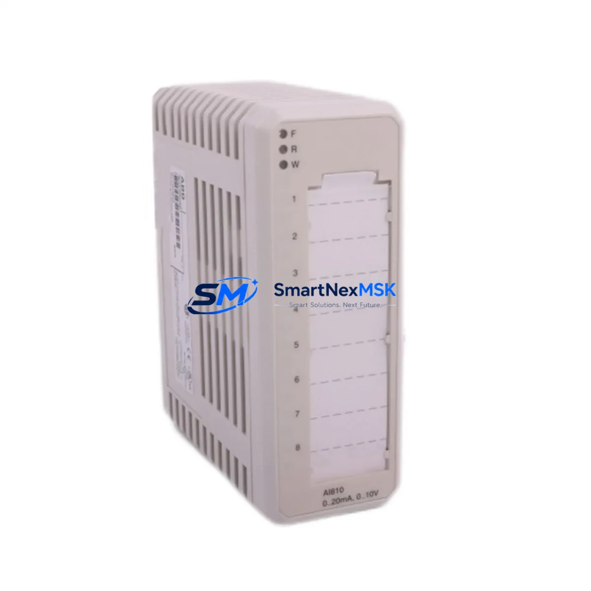
Whether your facility is migrating from an older ABB Advant or MOD 300 platform, upgrading a distributed I/O cabinet, or recovering from an unplanned module failure, the IDS-DTU51 provides a validated, drop-in compatible solution. Its 4–20 mA and 0–10 V analog input channels support direct connection to field transmitters including pressure, temperature, flow, and level instruments without requiring signal converter intermediaries. Each channel features galvanic isolation, ensuring signal integrity in electrically noisy industrial environments such as motor control centers and high-voltage switchgear rooms.
Before committing to a retrofit, engineers should verify several critical compatibility parameters. Power supply capacity within the existing control cabinet must be assessed — the IDS-DTU51 draws from the DTU Series backplane bus, and adding modules to a partially loaded rack requires confirming that the installed ABB DTU-PS24 or equivalent power supply unit has sufficient headroom. Terminal block wiring should be mapped against the original I/O schedule; the IDS-DTU51 uses a standard 40-pin front connector compatible with existing field cable assemblies in most DTU installations, eliminating the need for rewiring.
Backplane interface compatibility is equally important. The IDS-DTU51 is designed for the ABB DTU Series rack — typically the DTU-RK08 or DTU-RK16 chassis — and occupies a single slot. When replacing a failed module, the slot address is retained automatically upon insertion, provided the rack configuration has not been altered. If the rack has been reconfigured or the module address table in the controller has been modified, the ABB AC500 or AC31 series PLC managing the DTU rack will require a configuration download to re-establish the correct I/O mapping.
Program compatibility is a key concern during any analog input module swap. The IDS-DTU51 maintains the same data word structure and scaling conventions as its predecessors, meaning that existing ladder logic or function block programs written in ABB Control Builder or Automation Builder do not require modification in the majority of retrofit scenarios. However, engineers should validate channel scaling parameters — particularly engineering unit ranges and alarm setpoints — against the original module datasheet before returning the system to automatic control.
HMI screen updates are often overlooked during module replacements. If the facility uses an ABB CP600 or CP400 series operator panel, or a third-party SCADA system communicating via PROFIBUS DP or Modbus RTU, the analog input tags associated with the IDS-DTU51 channels should be verified against the HMI tag database. In most cases, tag addresses remain unchanged, but a forced I/O scan and live value comparison between the HMI display and a calibrated handheld instrument is recommended as part of the commissioning checklist.
Communication link integrity must be confirmed after module installation. The DTU Series communicates with the host controller via the ABB DDCS fiber-optic link or, in newer hybrid configurations, via PROFIBUS DP using an ABB CI840 or CI854 communication interface module. After inserting the IDS-DTU51, the communication status LED on both the module and the interface adapter should be verified before enabling automatic control loops. Any communication fault should be resolved before proceeding to loop tuning.
Field commissioning of the IDS-DTU51 follows a structured sequence: power-off insertion into the target rack slot, visual confirmation of backplane connector seating, power restoration, LED status verification (RUN green, ERR off), forced analog output test from the controller, live signal comparison at the field transmitter, and final loop calibration sign-off. This sequence minimizes the risk of introducing process upsets during the changeover and supports a controlled return to automatic operation.
For facilities managing spare parts inventory, stocking the IDS-DTU51 alongside complementary DTU Series components — including the ABB DTU-DO16 digital output module, DTU-DI16 digital input module, DTU-AO04 analog output module, and the DTU-PS24 power supply — provides comprehensive coverage for the most common failure modes in a DTU-based control cabinet. Pairing the IDS-DTU51 with an ABB CI854 PROFIBUS interface module and an ABB AC500 PM573 CPU ensures a complete, validated upgrade path for facilities transitioning from legacy Advant OCS or MOD 300 architectures to a modern, supported control platform.
Upgrade Compatibility Table
| Parameter | Details |
|---|---|
| Module SKU | IDS-DTU51 |
| Brand / Series | ABB / DTU Series |
| Module Type | Analog Input Module |
| Input Channels | Typically 8 × analog input (4–20 mA / 0–10 V) |
| Backplane / Rack Compatibility | ABB DTU-RK08, DTU-RK16 |
| Front Connector | 40-pin, compatible with existing DTU Series field wiring |
| Communication Interface | DDCS fiber-optic / PROFIBUS DP (via CI840 / CI854) |
| Host Controller Compatibility | ABB AC500, AC31, Advant OCS, MOD 300 (via gateway) |
| Programming Environment | ABB Control Builder, Automation Builder |
| Replacement for Legacy Models | DTU Series analog input predecessors; consult ABB cross-reference |
| Installation Requirement | Power-off insertion; slot address auto-retained |
| Commissioning Requirement | LED verification, forced I/O scan, loop calibration |
| Warranty | 12 Months — covers manufacturing defects and functional failure |
| Origin | China (CN) |
| Shipping | Global express; DHL / FedEx / UPS available |
Retrofit Planning for Existing Automation Systems
A successful IDS-DTU51 retrofit begins with a thorough audit of the existing control cabinet. Engineers should document the current rack population — noting which slots are occupied by the ABB DTU-DI16 digital input modules, DTU-DO16 digital output modules, DTU-AO04 analog output modules, and any DTU-PS24 power supply units — before ordering replacement or expansion modules. This audit prevents slot conflicts and ensures that the new IDS-DTU51 is assigned to the correct physical and logical address.
For facilities running mixed I/O architectures, the IDS-DTU51 can coexist in the same rack with digital and analog output modules without configuration conflicts, provided the rack’s total power budget is respected. The ABB DTU-PS24 power supply supports a defined maximum load per rack; exceeding this limit by adding modules without a power audit is a common cause of intermittent module faults and communication dropouts.
When the retrofit involves migrating from an older communication protocol — for example, moving from a proprietary DDCS fiber-optic link to PROFIBUS DP — the ABB CI854 PROFIBUS DP communication interface module must be installed in the rack alongside the IDS-DTU51. The CI854 handles protocol translation transparently, allowing the host ABB AC500 PM573 CPU to address the analog input channels using standard PROFIBUS GSD-based I/O mapping. An ABB programming cable (e.g., TK501 USB-to-serial adapter) is required to download the updated configuration to the controller during commissioning.
For HMI integration, facilities using ABB CP600 panels should verify that the analog input tags mapped to the IDS-DTU51 channels are correctly linked in the panel project. If the panel communicates via Modbus RTU, the register addresses for the analog input channels should be cross-checked against the updated controller I/O map before the panel is returned to service.
Downtime Control During System Migration
Minimizing unplanned downtime is the primary operational concern during any analog input module replacement. For the IDS-DTU51, the recommended approach is a planned maintenance window during a scheduled production shutdown, allowing the replacement to be completed under controlled conditions without time pressure.
Before powering down the rack, the current analog input values for all channels on the module being replaced should be recorded — either from the SCADA historian or from a handheld instrument at the field transmitter. These reference values serve as the baseline for post-installation verification. If the process cannot be taken offline, the host controller should be placed in manual mode for the affected control loops, with operators maintaining setpoints manually at the HMI until the new module is commissioned and verified.
The IDS-DTU51’s slot-address retention feature significantly reduces commissioning time: because the module inherits the slot address of its predecessor automatically, no controller configuration download is required in standard replacement scenarios. This means the total changeover time — from power-off to return-to-automatic — can typically be completed within a single shift, provided all preparatory steps (wiring documentation, spare module availability, calibration tools) are completed in advance.
After installation, a structured loop check — comparing live analog input readings at the controller against calibrated reference signals injected at the field terminal — confirms that all channels are functioning within specification before the control loops are returned to automatic. This final verification step, combined with a 30-minute observation period in manual mode, provides confidence that the retrofit has been completed successfully and that process continuity is maintained.
Retrofit Support FAQ
Q1: Is the IDS-DTU51 a direct drop-in replacement for the previous DTU Series analog input module?
In most DTU Series rack configurations, yes. The IDS-DTU51 uses the same backplane connector, slot form factor, and I/O data structure as its predecessors. However, engineers should verify the specific legacy model number against ABB’s cross-reference documentation to confirm full compatibility before installation.
Q2: What wiring changes are required when installing the IDS-DTU51?
In standard retrofit scenarios, no wiring changes are required. The IDS-DTU51’s 40-pin front connector is compatible with existing DTU Series field cable assemblies. If the installation involves expanding I/O capacity rather than replacing a failed module, new field wiring to the additional channels will be required, following the terminal assignment diagram in the IDS-DTU51 hardware manual.
Q3: Does the IDS-DTU51 require a firmware or software update on the host controller?
Not in standard replacement scenarios. The IDS-DTU51 is recognized automatically by the ABB AC500 or AC31 controller upon insertion, and existing program logic does not require modification. A configuration download is only required if the rack slot assignment has changed or if the module is being added to a previously unoccupied slot.
Q4: What does the 12-month warranty cover, and what is the process for a warranty claim?
The 12-month warranty covers manufacturing defects and functional failure under normal operating conditions. To initiate a warranty claim, contact sales@smartnexmsk.com with the module serial number, purchase date, and a description of the fault. Replacement units are dispatched after fault verification, with express shipping available to minimize production downtime.
© 2026 SMARTNEXMSK. All rights reserved.
Original Source: https://smartnexmsk.com
Contact: sales@smartnexmsk.com | +86 18259474341


