ABB LD LPTR-01 Retrofit-Ready Gate Driver for LD Series Control Systems
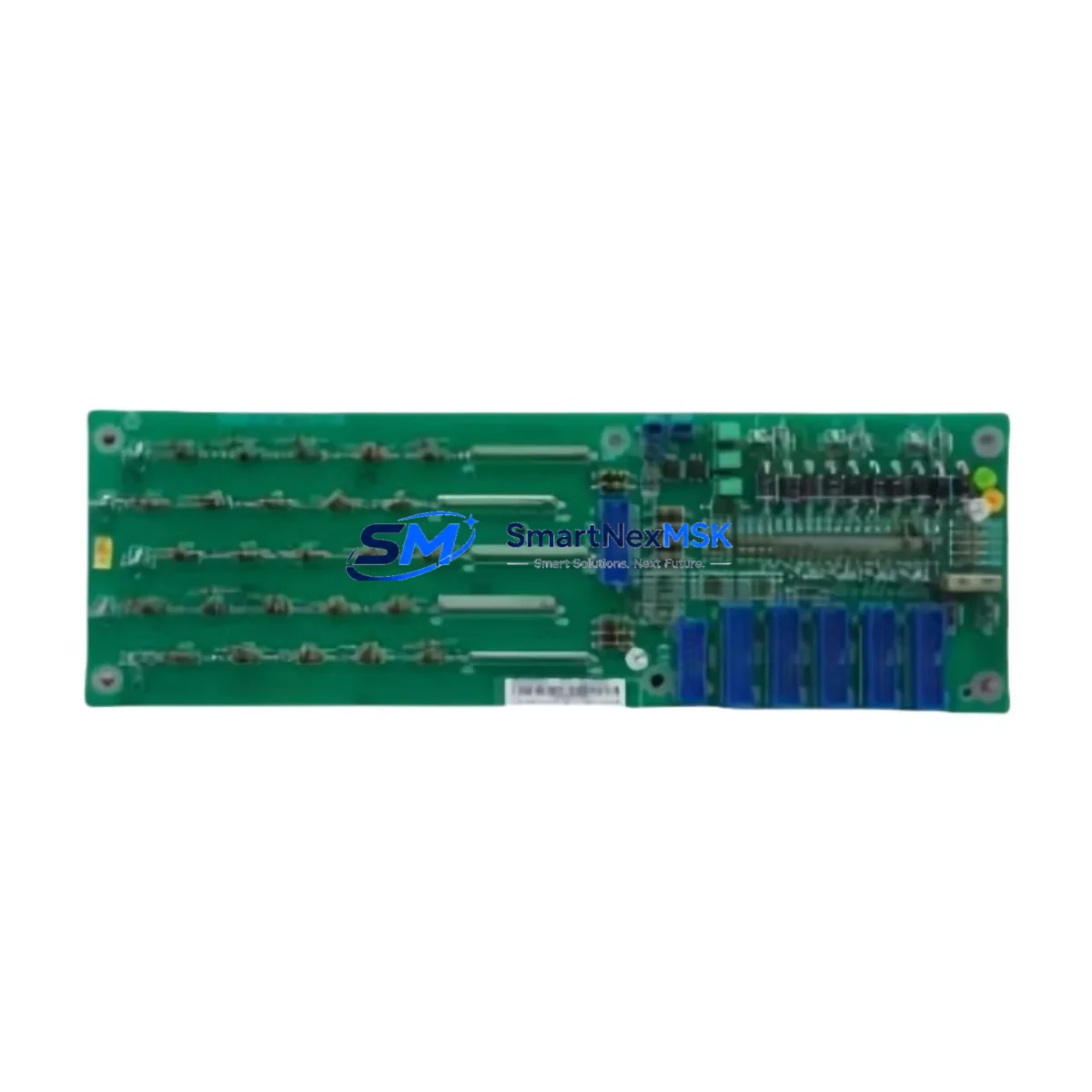
The ABB LD LPTR-01 is a pulse transformer-based gate driver isolation module engineered for ABB’s LD Series AC drive platforms. As legacy LD Series installations age and original spare parts become increasingly difficult to source, the LD LPTR-01 serves as a verified retrofit-ready replacement that enables engineers to restore full drive functionality without redesigning the control cabinet or rewriting existing PLC programs. Whether you are managing a planned upgrade cycle or responding to an unplanned drive fault, this module is stocked and ready to ship with a 12-month warranty covering manufacturing defects and functional performance.
In retrofit and modernization projects, the LD LPTR-01 is typically installed alongside other LD Series drive components such as the LD SINT-41C DDCS fiber optic communication board, the LD AINT-02 analog I/O extension module, and the LD DINT-01 digital input terminal board. These modules share the same backplane architecture and power distribution rail, which means that a gate driver replacement can be completed without disturbing the surrounding I/O wiring or communication links. Engineers replacing the LD LPTR-01 should verify the DC bus voltage level and confirm that the IGBT gate signal timing parameters stored in the drive’s FLASH memory remain compatible with the replacement module’s isolation characteristics before powering up.
For sites running ABB’s DriveWindow or DriveStudio commissioning software, the LD LPTR-01 does not require a separate firmware upload — the gate driver parameters are managed at the inverter control board level, typically the LD AINT or LD RMIO board depending on the drive generation. Technicians should confirm the RMIO board firmware version and cross-reference the gate driver specification table in the LD Series hardware manual before finalizing the swap. If the site also uses an ABB ACS800 or ACS600 series drive in the same control room, note that those platforms use different gate driver modules (such as the AINT-02 or DINT-02 families) and the LD LPTR-01 is not cross-compatible with those chassis.
Upgrade Compatibility Table
| Parameter | Detail |
|---|---|
| SKU | LD LPTR-01 |
| Brand | ABB |
| Series | LD Series AC Drive |
| Module Function | Gate Driver Pulse Transformer / IGBT Isolation |
| Replaces | ABB LD LPTR-01 (OEM and discontinued stock) |
| Backplane Interface | LD Series standard drive backplane connector |
| Installation Type | Direct plug-in, no mechanical modification required |
| Communication Compatibility | Compatible with DDCS fiber optic and RMIO control board |
| Commissioning Requirement | Parameter verification via DriveWindow / DriveStudio |
| Origin | Germany |
| Warranty | 12 Months — covers manufacturing defects and functional performance |
| Retrofit Recommendation | Verify IGBT gate timing and DC bus voltage before energizing |
Retrofit Planning for Existing Automation Systems
A successful LD LPTR-01 retrofit begins well before the module arrives on site. The first step is a full audit of the existing drive cabinet: document the current LD Series drive firmware version, record all active fault codes from the drive’s event log, and photograph the existing terminal wiring on the LD AINT-02 analog I/O board and the LD DINT-01 digital input board. This documentation becomes the baseline for post-replacement verification and protects the engineering team if a commissioning dispute arises.
Power supply integrity is the next critical checkpoint. The LD Series drive’s internal 24 VDC auxiliary power supply — often sourced from an ABB PSU or a third-party DIN-rail SMPS unit mounted in the same cabinet — must be confirmed stable before the gate driver is replaced. A voltage sag or ripple on the 24 VDC rail during the replacement window can corrupt the RMIO board’s parameter memory, requiring a full parameter restore from backup. If the site does not have a recent parameter backup, use DriveStudio to export the full parameter set before beginning any hardware work.
Terminal wiring on the LD LPTR-01 is straightforward, but technicians should pay close attention to the gate signal cable routing. The pulse transformer’s primary winding connects to the inverter control board via a short ribbon or discrete wire harness; any mechanical stress on this connection during module removal can damage the control board’s gate output stage. Use a connector extraction tool rather than pulling the harness by hand. After seating the replacement LD LPTR-01, verify connector lock engagement before applying power.
Sites that also operate ABB SAMI or older LD Series drives with DDCS fiber optic rings should confirm that the optical link between the LD SINT-41C communication board and the upstream PLC or DCS remains intact throughout the replacement. A fiber optic link interruption during a hot-standby system changeover can trigger a process interlock that is difficult to reset without HMI intervention. Coordinate with the control room operator before isolating the drive, and confirm that the HMI screen associated with the drive’s status tag is displaying the correct pre-maintenance state.
Downtime Control During System Migration
Minimizing unplanned downtime during an LD LPTR-01 replacement requires a structured pre-work checklist and a clearly defined go/no-go decision point. The recommended approach is to stage the replacement during a scheduled maintenance window, with the replacement module pre-tested on a bench power supply to confirm gate signal output before it enters the cabinet. Bench testing takes approximately 15 minutes and eliminates the risk of installing a transit-damaged unit into a live system.
Before de-energizing the drive, confirm that the process line controlled by the LD Series drive is in a safe hold state and that any upstream or downstream equipment interlocked with the drive’s run signal has been notified. If the drive is part of a coordinated multi-drive system — for example, a winder or conveyor line where multiple LD Series drives share a common speed reference via the DDCS ring — the entire drive group may need to be placed in manual speed control mode before the affected drive is isolated.
After the LD LPTR-01 is replaced and the drive is re-energized, perform a no-load run test at low speed (typically 5–10 Hz) before restoring the process load. Monitor the drive’s output current waveform on the keypad or via DriveWindow to confirm that all three phases are balanced and that no gate fault codes (such as fault 0009 or 0010 in the LD Series fault dictionary) are active. Once the no-load test passes, ramp the drive to full speed under load and confirm that the process variable — flow, pressure, tension, or speed — returns to its pre-maintenance setpoint. Total replacement time for a prepared technician is typically 45–90 minutes, keeping production impact to a single shift window.
Retrofit Support FAQ
Q1: Is the LD LPTR-01 a direct drop-in replacement for the original ABB part?
Yes. The LD LPTR-01 supplied by SMARTNEXMSK is dimensionally and electrically equivalent to the original ABB factory part. It uses the same backplane connector, the same pulse transformer isolation ratio, and the same gate signal interface as the OEM module. No mechanical modification or parameter change is required for a standard replacement on an unmodified LD Series drive.
Q2: What commissioning steps are required after installation?
After seating the module and restoring power, navigate to the drive’s fault log and confirm no new gate driver faults are present. Perform a no-load run at low frequency and verify balanced three-phase output current. If the drive was previously running a custom motor model or auto-tuned parameters, confirm those values are still present in the parameter list — they should be unaffected by a gate driver swap, but verification is best practice before returning the drive to production.
Q3: How do I verify wiring compatibility before installation?
Compare the gate signal harness connector on the existing LD LPTR-01 with the replacement unit before removing the old module. Both should have identical pin count and keying. If the existing harness shows signs of heat damage or insulation cracking, replace the harness at the same time as the module — a degraded harness can cause intermittent gate faults that are difficult to diagnose after the fact.
Q4: What does the 12-month warranty cover?
The 12-month warranty covers manufacturing defects and functional performance failure under normal operating conditions. It does not cover damage caused by incorrect installation, overvoltage events, or operation outside the module’s rated specifications. All units are function-tested before shipment. If a warranty claim is required, contact SMARTNEXMSK with the order number and a description of the fault; replacement or refund is processed within 5 business days of fault confirmation.
© 2026 SMARTNEXMSK. All rights reserved.
Original Source: https://smartnexmsk.com
Contact: sales@smartnexmsk.com | +86 18259474341


