ABB NDBU-85C Maintenance-Ready Spare for ACS800 Automation
The ABB NDBU-85C is a Fieldbus Branch Unit designed for use in ACS800 multi-drive cabinet systems, enabling distributed fieldbus communication across multiple drive units from a single master connection. In industrial environments where ACS800 drives control critical motor loads — pumps, compressors, conveyors, hoists, and HVAC systems — the NDBU-85C serves as the communication backbone that links each drive’s RDCO-0x communication option board to the plant-level fieldbus network. A failure or degradation of this unit can isolate multiple drives simultaneously, triggering a cascade of process alarms and unplanned downtime. Holding a verified original spare in your maintenance inventory is the most effective single action to protect against this scenario.
This listing supplies an original ABB NDBU-85C, sourced from authorized industrial channels, pre-tested before dispatch, and covered by a 12-month warranty. Units are shipped with full inspection documentation and are ready for immediate installation into ACS800 multi-drive cabinets.
Spare Maintenance Table
| Parameter | Specification |
|---|---|
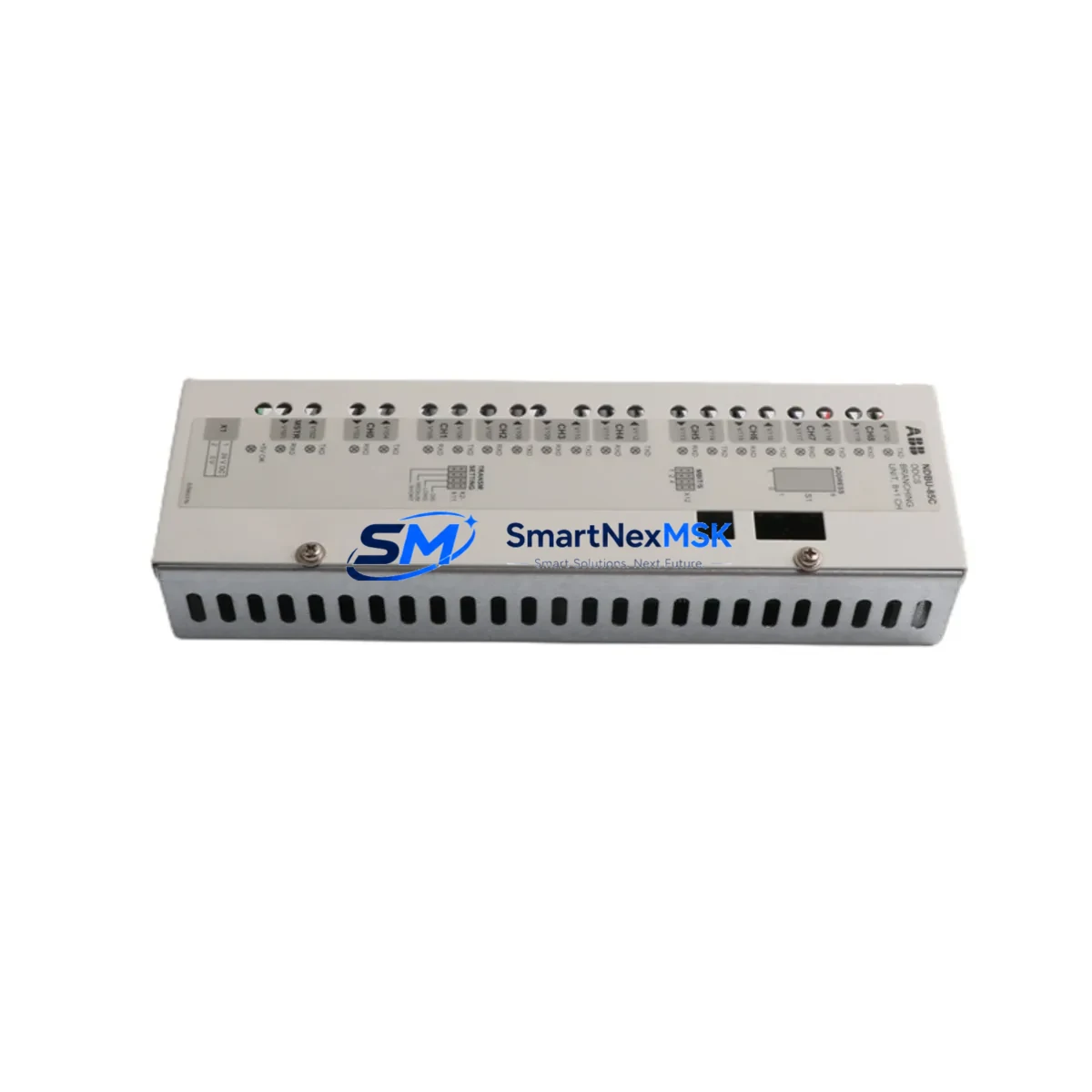
| Part Number | NDBU-85C |
| Manufacturer | ABB |
| Series Compatibility | ACS800 Multi-Drive Systems |
| Function | Fieldbus Branch Unit — distributes fieldbus signals to up to 12 drive units |
| Supported Fieldbus Adapters | RDCO-01 (DDCS), compatible with RPBA, RFBA, RETA series via RDCO |
| Optical Fiber Channels | Up to 12 drive branches (DDCS optical ring) |
| Supply Voltage | 24 VDC (from ACS800 control board or external 24 V supply) |
| Operating Temperature | 0 °C to +55 °C |
| Mounting | DIN rail or panel mount inside ACS800 multi-drive cabinet |
| Country of Origin | Finland |
| Weight | Approx. 720 g (with packaging) |
| Condition | Original, new or tested-serviceable |
| Warranty | 12 Months — covers manufacturing defects and functional failure |
| Pre-Shipment Test | Power-on, optical channel continuity, and communication handshake verified |
| Typical Application | ACS800 multi-drive cabinets in process industries, marine, and infrastructure |
Maintenance Planning for Continuous Operation
When a maintenance or reliability engineer schedules a planned inspection or responds to a fieldbus communication fault on an ACS800 multi-drive system, the NDBU-85C is rarely the only component that warrants attention. The unit sits at the center of a communication chain, and its health is directly dependent on the integrity of the components upstream and downstream of it.
During any cabinet inspection that involves the NDBU-85C, engineers should simultaneously verify the condition of the RDCO-01 or RDCO-02 communication option boards installed in each individual ACS800 drive unit — these boards form the optical DDCS ring that the NDBU-85C manages, and a degraded RDCO board can produce intermittent faults that are misdiagnosed as branch unit failures. The APBU-44C or APBU-12C pulse encoder interface units, if present in the same cabinet, share the same 24 VDC auxiliary supply rail and should be checked for supply voltage stability.
The 24 VDC auxiliary power supply module feeding the NDBU-85C and associated option boards is a high-priority inspection item — undervoltage on this rail is a leading cause of communication dropouts that appear as NDBU-85C faults. Alongside this, inspect the AGPS-11C or AGPS-21C gate driver power supply boards within each drive module for signs of capacitor aging or thermal stress.
Optical fiber patch cables connecting the NDBU-85C to each drive’s RDCO board are a common wear item in high-vibration or high-temperature cabinet environments. Stocking a set of DDCS optical fiber jumpers (typically NKOC-xx series) alongside the NDBU-85C spare is standard practice in facilities with multiple ACS800 cabinets. Similarly, the AINT-xx inverter control boards and AINP-xx pulse encoder interface boards within each drive module should be logged in the spare parts register, as their failure can produce symptoms that overlap with communication faults.
For sites running ACS800 systems with profibus or DeviceNet integration, the RPBA-01 PROFIBUS DP adapter or RDNA-01 DeviceNet adapter modules connected upstream of the NDBU-85C should be included in the annual inspection checklist. Finally, the CDP312R control panel or connected HMI terminal used for drive parameter access and fault history review should be confirmed operational before and after any NDBU-85C replacement, as it is the primary tool for verifying restored communication status.
Site Replacement Workflow
Step 1 — Fault Isolation: Identify which branch of the DDCS ring has lost communication using the ACS800 drive’s fault log (fault code COMM ERR or similar). The NDBU-85C LED indicators provide per-channel status; a dark or red LED on a specific channel confirms the affected branch.
Step 2 — Safe Isolation: Follow site LOTO (Lockout/Tagout) procedures. The NDBU-85C operates on 24 VDC and can be replaced without de-energizing the main DC bus in some cabinet configurations, but always confirm with the site electrical safety plan before proceeding.
Step 3 — Physical Replacement: Disconnect optical fiber cables from the affected channels, noting their positions. Remove the NDBU-85C from its DIN rail or panel mount. Install the replacement unit, reconnect fibers in the same channel positions, and restore 24 VDC supply.
Step 4 — Communication Verification: Power on and observe LED status on the replacement NDBU-85C. Use the CDP312R panel or connected SCADA/DCS to confirm that all previously faulted drives have re-established communication. Check drive parameter group 70 (DDCS control) on each ACS800 to confirm node addresses and communication status are correct.
Step 5 — System Handback: Run a no-load test cycle on each drive branch before returning the system to production. Log the replacement in the site maintenance management system (CMMS) and update the spare parts inventory to trigger reorder of a replacement NDBU-85C unit.
This workflow is compatible with both direct NDBU-85C-to-NDBU-85C replacement and with upgrades from earlier NDBU-21C or NDBU-41C variants, which share the same mounting footprint and optical channel layout but differ in maximum branch count.
Spare Parts Support FAQ
Q: Is this NDBU-85C compatible with all ACS800 multi-drive cabinet configurations?
A: The NDBU-85C supports up to 12 DDCS optical branches and is compatible with ACS800-07, ACS800-17, ACS800-37, and ACS800-104 multi-drive configurations. Single-drive ACS800 units do not use the NDBU-85C. Confirm your cabinet’s branch count before ordering to ensure the -85C variant (12-branch) is appropriate versus the -41C (4-branch) or -21C (2-branch).
Q: What pre-shipment testing is performed on this unit?
A: Each NDBU-85C is powered on and subjected to optical channel continuity testing across all 12 branches, 24 VDC supply current draw verification, and a DDCS communication handshake test before dispatch. A test report is available on request.
Q: How should the NDBU-85C be stored as a long-term cabinet spare?
A: Store in original anti-static packaging in a dry environment between -40 °C and +70 °C with relative humidity below 95% non-condensing. Avoid storage near strong magnetic fields or high-vibration areas. Inspect optical connectors for dust contamination annually and clean with appropriate fiber optic cleaning tools before installation.
Q: What does the 12-month warranty cover?
A: The warranty covers manufacturing defects and functional failure under normal operating conditions for 12 months from the date of shipment. It does not cover damage resulting from incorrect installation, overvoltage events, or physical impact. Warranty claims are processed with return shipping support and replacement dispatch within 5 business days of fault confirmation.
© 2026 SMARTNEXMSK. All rights reserved.
Original Source: https://smartnexmsk.com
Contact: sales@smartnexmsk.com | +86 18259474341


