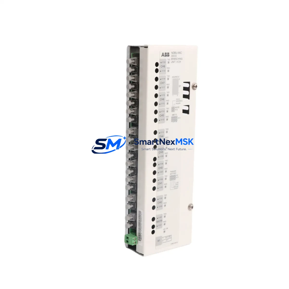
ABB NDBU-95C 3AFE64008366 Retrofit-Ready DDCS Branching Unit for ACS800 Control Systems
The ABB NDBU-95C (Part No. 3AFE64008366) is a DDCS (Distributed Drives Communication System) fiber-optic branching unit engineered for multi-drive communication architectures within ABB’s ACS800 industrial drive platform. As legacy ACS800 installations age and original NDBU-95 units reach end-of-life, the NDBU-95C serves as the direct retrofit-ready replacement — preserving existing fiber-optic wiring, DDCS ring topology, and drive-to-controller communication without requiring panel redesign or software re-engineering.
This unit supports up to 12 DDCS fiber-optic channels, enabling a single master controller — such as an RDCO-02 or RDCO-04 DDCS communication module mounted on an ACS800 inverter unit — to communicate with multiple follower drives across a high-speed optical ring. The NDBU-95C is fully compatible with ABB’s ACS800-01, ACS800-04, ACS800-07, and ACS800-11 drive variants, as well as multi-drive cabinet configurations using the ACS800-17 and ACS800-37 series.
Upgrade Compatibility Table
| Parameter | NDBU-95 (Legacy) | NDBU-95C 3AFE64008366 (Retrofit) |
|---|---|---|
| DDCS Channels | Up to 12 | Up to 12 (identical) |
| Fiber-Optic Interface | ST-type connectors | ST-type connectors (direct swap) |
| Mounting | DIN rail / panel | DIN rail / panel (same footprint) |
| Supply Voltage | 24 VDC | 24 VDC (same terminal block) |
| Communication Protocol | DDCS (proprietary ABB optical) | DDCS (fully compatible) |
| Replacement Recommendation | — | Direct 1:1 replacement; no firmware change required |
| Commissioning Focus | Node address DIP switches | Verify node address DIP switches match original unit |
| Warranty | — | 12-Month Warranty included |
Retrofit Planning for Existing Automation Systems
Replacing an NDBU-95C in a live ACS800 multi-drive system requires careful pre-outage planning to ensure a smooth cutover. Before scheduling the maintenance window, engineers should document the existing DDCS ring topology — recording which fiber-optic port on the branching unit connects to each follower drive’s RDCO-02 or RDCO-04 communication adapter. Labeling each ST-type fiber cable before disconnection eliminates reconnection errors during the swap.
Power supply verification is the next critical step. The NDBU-95C draws its 24 VDC supply from the control cabinet’s auxiliary power rail, typically shared with other low-voltage components such as the APBU-44C auxiliary power branching unit and the AINT-02 or AINT-14 inverter interface boards. Confirm that the 24 VDC rail has sufficient current capacity to support the replacement unit without voltage droop, particularly in cabinets where multiple RDIO-01 digital I/O extension modules or RAIO-01 analog I/O modules are also powered from the same bus.
For systems where the ACS800 master drive communicates upstream to a DCS or PLC via a fieldbus adapter — such as the RPBA-01 PROFIBUS-DP adapter or RCAN-01 CANopen adapter — the DDCS ring must be fully restored before the fieldbus link is re-enabled. Failure to restore the DDCS ring first can cause the master drive to report a communication fault and trip the entire drive line.
In multi-cabinet installations, the NDBU-95C may also interface with an NDBU-85C branching unit used in a sub-ring configuration. Verify that the sub-ring node addresses are correctly set on both the NDBU-95C and the NDBU-85C after replacement, as mismatched node addresses are the most common cause of post-retrofit DDCS communication faults. The node address is set via DIP switches on the front face of the unit and must match the address previously configured in the ACS800 drive parameters (parameter group 70 in the ACS800 firmware).
Panel-level documentation should also be updated to reflect the new part number (3AFE64008366) and the replacement date, supporting future maintenance cycles and spare-parts planning. Where the original installation used an NPBU-12C or NPBU-22C panel bus branching unit alongside the NDBU-95C, confirm that the panel bus wiring and termination resistors remain intact after the DDCS fiber swap.
Downtime Control During System Migration
Minimizing unplanned downtime during an NDBU-95C replacement begins with a structured pre-outage backup. Use the ACS800’s DriveWindow Light 2 or DriveWindow 2 PC tool to upload and save all drive parameter sets from every node on the DDCS ring before the maintenance window opens. Store backups on a dedicated engineering laptop and verify file integrity before proceeding. This ensures that if any drive loses its parameter set during the power cycle, restoration takes minutes rather than hours.
During the physical swap, the NDBU-95C’s identical mechanical footprint and terminal layout allow the replacement unit to be installed in the same DIN rail position without any panel modification. Reconnect the 24 VDC supply terminals first, then reconnect the fiber-optic ST connectors in the documented port order. Power up the branching unit before energizing the ACS800 drives to allow the DDCS ring to initialize and stabilize.
After power-up, verify DDCS ring integrity using the ACS800 master drive’s diagnostic parameters (parameter 70.01 through 70.06) before releasing the system to automatic control. If any follower drive reports a DDCS communication fault (fault code DDCS LINK), check the fiber-optic connection at the corresponding NDBU-95C port and confirm the node address DIP switch setting on that drive’s RDCO adapter. In most cases, faults clear within 30 seconds of correct fiber reconnection without requiring a drive restart.
For production lines where even a brief interruption is critical, consider pre-staging the replacement NDBU-95C with the correct node address DIP switch settings and 24 VDC terminal pre-wired on a sub-panel, allowing the physical swap to be completed in under 10 minutes. All units supplied by SMARTNEXMSK are pre-tested under load conditions prior to shipment, reducing the risk of DOA units and supporting a first-time-right installation outcome.
Retrofit Support FAQ
Q1: Is the NDBU-95C 3AFE64008366 a direct replacement for the original NDBU-95?
Yes. The NDBU-95C is ABB’s updated revision of the NDBU-95 branching unit and is a direct 1:1 mechanical and electrical replacement. The fiber-optic port layout, DIN rail mounting dimensions, 24 VDC supply terminals, and DDCS protocol compatibility are identical. No firmware changes or parameter modifications are required in the ACS800 drives after replacement.
Q2: What commissioning checks are required after installing the NDBU-95C?
After installation, verify: (1) DIP switch node address matches the original unit; (2) all ST-type fiber-optic cables are reconnected to the correct ports as per the pre-outage documentation; (3) 24 VDC supply is within tolerance (20.4–28.8 VDC); (4) ACS800 master drive parameters 70.01–70.06 confirm all DDCS nodes are online. No additional calibration is required.
Q3: Can the NDBU-95C be used with ACS800 drives that use PROFIBUS or DeviceNet fieldbus adapters?
Yes. The NDBU-95C operates at the DDCS layer, which is independent of the fieldbus adapter installed on the master drive. Whether the ACS800 uses an RPBA-01 PROFIBUS-DP adapter, an RDNA-01 DeviceNet adapter, or an RECA-01 EtherCAT adapter for upstream PLC communication, the DDCS ring managed by the NDBU-95C functions independently and does not require reconfiguration when the branching unit is replaced.
Q4: What warranty and pre-shipment testing does SMARTNEXMSK provide?
Every NDBU-95C unit supplied by SMARTNEXMSK is covered by a 12-month warranty from the date of shipment. Prior to dispatch, each unit undergoes functional testing including DDCS signal integrity verification and 24 VDC power input validation. Units are shipped in anti-static packaging with full documentation. For urgent retrofit projects, expedited shipping options are available — contact our team to confirm lead times and stock availability.
© 2026 SMARTNEXMSK. All rights reserved.
Original Source: https://smartnexmsk.com
Contact: sales@smartnexmsk.com | +86 18259474341


