ABB NDBU-95C 64008366 Spare for AC800M Automation: Fiber Optic Branching Unit for Industrial Downtime Recovery
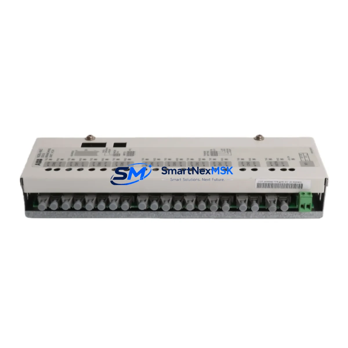
The ABB NDBU-95C (catalog reference 64008366) is a 9-channel DDCS fiber optic branching unit designed for high-reliability communication in ABB’s AC800M, ACS800, and DCS800 control architectures. As a maintenance-ready original spare, the NDBU-95C plays a critical role in sustaining the fiber optic backbone of distributed drive and process control systems. When this component fails or degrades, the entire DDCS communication ring can collapse, triggering cascading faults across connected drives, I/O modules, and supervisory controllers. Stocking a verified replacement unit is the single most effective measure a maintenance team can take to minimize unplanned downtime in ABB-based automation environments.
For maintenance engineers managing aging ABB control cabinets, the NDBU-95C is often the silent backbone of multi-drive coordination. It bridges the DDCS fiber ring between the AC800M controller and downstream frequency converters such as the ACS800 or ACS880 series, as well as DCS800 DC drives. A fault in the branching unit — whether from fiber connector contamination, optical power degradation, or board-level component failure — will manifest as communication loss alarms, drive trip events, or complete loss of speed reference to coordinated drive groups. Rapid identification and replacement of the NDBU-95C is therefore a core competency for any site running ABB DDCS-based systems.
Spare Maintenance Table
| Parameter | Specification |
|---|---|
| Part Number | NDBU-95C |
| Catalog / Order Code | 64008366 |
| Manufacturer | ABB |
| Country of Origin | Finland |
| Function | 9-Channel DDCS Fiber Optic Branching Unit |
| Communication Protocol | DDCS (Distributed Drives Communication System) |
| Fiber Channels | 9 (1 master + 8 branch) |
| Fiber Type | Plastic optical fiber (POF), 1 mm |
| Compatible Controllers | AC800M, RDCO-0x, RDCO-03 |
| Compatible Drives | ACS800, ACS880, DCS800, ACS600 |
| Supply Voltage | 24 V DC (from drive control board) |
| Operating Temperature | 0 °C to +55 °C |
| Mounting | DIN rail or panel mount |
| Product Condition | Original, new or tested-good surplus |
| Pre-shipment Testing | Yes – optical continuity and power verified |
| Warranty | 12 Months |
| Lead Time | In stock – ships within 1–3 business days |
Maintenance Planning for Continuous Operation
When a maintenance or procurement engineer schedules replacement of the NDBU-95C, the scope of inspection should extend beyond the branching unit itself. The DDCS fiber ring is an integrated communication system, and a single degraded component can mask or cause faults in adjacent hardware. A thorough site replacement workflow should include the following checks:
Begin with the RDCO-03 or RDCO-04 DDCS communication option board installed in the ACS800 or DCS800 drive. This board is the physical interface between the drive’s control electronics and the DDCS fiber ring; if the NDBU-95C has been running in a degraded state, the RDCO board may have logged repeated communication errors or sustained optical receiver stress. Inspect and test the RDCO board in parallel with the branching unit replacement.
Next, verify the NPOW-41C or NPOW-51C power supply module that feeds the NDBU-95C and associated I/O extension modules. A sagging 24 V DC rail is a common root cause of intermittent DDCS communication faults that are incorrectly attributed to the branching unit. Measure supply voltage under load before declaring the NDBU-95C as the sole fault source.
Inspect all plastic optical fiber (POF) patch cables connecting the NDBU-95C to the drive RDCO boards. POF cables are susceptible to bend radius violations, connector contamination, and UV degradation in exposed cabinet environments. Replace any cable showing visible yellowing, cracking, or measured optical loss above the system threshold. Carry spare POF cables of standard lengths (0.5 m, 1 m, 2 m) alongside the NDBU-95C in your critical spares kit.
For systems using NAMC-11 or NAMC-03 motor control boards in the ACS800, confirm that the board’s DDCS node address is correctly set after the branching unit is replaced and the ring is re-initialized. Node address conflicts are a frequent commissioning error following emergency replacements performed under time pressure.
If the control cabinet also houses NINT-41C or NINT-72C inverter control boards, these should be visually inspected for signs of thermal stress or capacitor bulging during the same maintenance window. Combining inspections reduces future downtime risk and maximizes the value of each planned outage.
For sites running AC800M controllers with PM861 or PM864 processor modules, verify that the controller’s DDCS master port optical output power is within specification after the new NDBU-95C is installed. A weak master port signal will cause marginal communication on long fiber runs even with a healthy branching unit.
Finally, review the status of NAIO-03 analog I/O extension modules and NDIO-01 digital I/O modules connected downstream of the NDBU-95C. These modules rely on the DDCS ring for all process data exchange; any that were offline during the fault period should be power-cycled and their configuration verified against the system backup before returning the line to production.
Site Replacement Workflow
Step 1 – Isolate and document. Before removing the NDBU-95C, record all fiber channel assignments, node addresses, and cable routing. Photograph the existing installation. This documentation is essential for rapid re-commissioning and for training future maintenance personnel.
Step 2 – Power down safely. De-energize the control cabinet following site LOTO procedures. The NDBU-95C is powered from the drive’s 24 V DC auxiliary supply; confirm the supply is isolated before disconnecting fiber connectors or removing the unit from its mounting.
Step 3 – Replace and reconnect. Install the new NDBU-95C in the same mounting position. Reconnect all POF fiber cables in the original channel order. Ensure connectors are fully seated and locking clips are engaged. Clean connector faces with an appropriate fiber optic cleaning tool before insertion.
Step 4 – Power up and verify. Restore 24 V DC supply and observe the NDBU-95C status LEDs. All active channels should indicate a valid optical link within seconds of power-up. Access the AC800M or drive panel to confirm DDCS communication is re-established and no node is reporting a fault.
Step 5 – Functional test before production restart. Run the drive system in local/manual mode to verify speed reference, feedback, and I/O signals are operating correctly before returning to automatic production control. Log the replacement in the site maintenance management system with the new unit’s serial number and installation date.
This workflow is applicable whether the NDBU-95C is replacing a failed unit on an emergency basis or being installed as part of a planned preventive maintenance cycle. The same procedure supports legacy system life extension programs where original ABB hardware is being refreshed to extend operational life by 5–10 years without a full system migration.
Spare Parts Support FAQ
Q1: Is this NDBU-95C (64008366) a genuine ABB original part?
Yes. All units supplied are original ABB manufacture, sourced from authorized distribution or verified surplus channels. Each unit undergoes pre-shipment optical and electrical testing. A 12-month warranty is provided from the date of dispatch, covering manufacturing defects and functional failure under normal operating conditions.
Q2: What is the recommended spare parts inventory strategy for the NDBU-95C?
For sites operating more than three ACS800 or DCS800 drives on a single DDCS ring, we recommend holding a minimum of one NDBU-95C as a critical on-site spare. For larger installations or sites with extended lead times from local distributors, two units provide adequate coverage for both emergency replacement and planned maintenance rotation. The NDBU-95C is a long-lead item through standard ABB channels; maintaining your own stock eliminates procurement delays during unplanned outages.
Q3: Can the NDBU-95C replace older NDBU-85C or NDBU-55C units?
The NDBU-95C is the current-generation 9-channel DDCS branching unit and is backward-compatible with systems previously using the NDBU-85C (8-channel) in most configurations. Physical mounting dimensions and fiber connector types are identical. Node address configuration and DDCS ring topology should be verified against the system documentation before substitution. Contact our technical team with your system configuration details for a compatibility confirmation prior to ordering.
Q4: What testing is performed before shipment?
Each NDBU-95C is tested for optical output power on all 9 channels, 24 V DC power consumption within specification, and visual inspection of the PCB, connectors, and housing. Units that do not meet ABB’s original performance parameters are not dispatched. A test report is available upon request for critical applications. All units are packed in anti-static packaging with protective caps on all fiber connectors to prevent contamination during transit.
© 2026 SMARTNEXMSK. All rights reserved.
Original Source: https://smartnexmsk.com
Contact: sales@smartnexmsk.com | +86 18259474341


