ABB PDP800 DP-V2 Maintenance-Ready Spare AC500: Spare Replacement & Industrial Downtime Risk Control
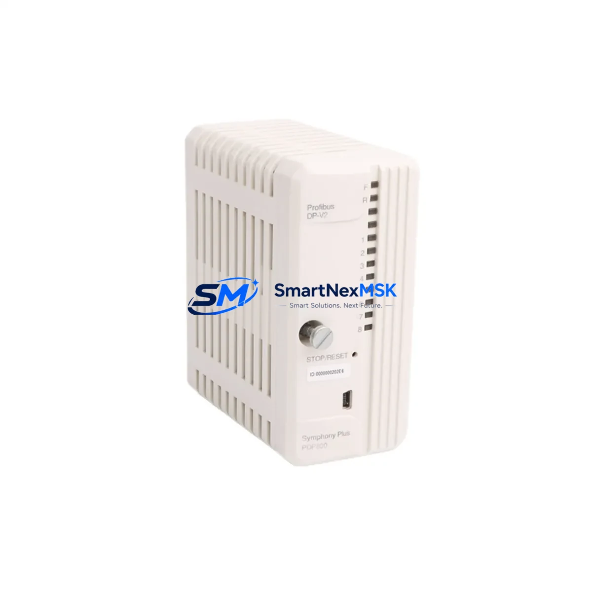
The ABB PDP800 DP-V2 is an original PROFIBUS DP-V2 interface module designed for the ABB AC500 and S500 PLC platform. In industrial automation environments — from process plants and water treatment facilities to automotive assembly lines and power distribution substations — the PDP800 DP-V2 serves as the critical communication bridge between the AC500 CPU and PROFIBUS DP field devices. When this module fails or degrades, the entire PROFIBUS segment goes offline, triggering unplanned downtime that can cost thousands of dollars per hour.
Stocking a verified replacement unit of the PDP800 DP-V2 is a fundamental element of any proactive maintenance strategy. Whether you are managing a planned shutdown, responding to an emergency fault, or conducting a scheduled control cabinet inspection, having this module on your spare parts shelf eliminates the lead time risk associated with last-minute procurement. SMARTNEXMSK supplies original ABB PDP800 DP-V2 modules with full functional testing prior to shipment and a 12-month warranty covering manufacturing defects and operational failures under normal industrial conditions.
Spare Maintenance Table
| Parameter | Specification |
|---|---|
| Part Number / SKU | PDP800 DP-V2 |
| Brand | ABB |
| Series Compatibility | AC500, S500 (PM571, PM581, PM591, PM595 CPUs) |
| Communication Protocol | PROFIBUS DP-V2 (IEC 61158) |
| Module Type | PROFIBUS DP-V2 Interface / Communication Module |
| Mounting | Direct plug-in to AC500 CPU or S500 I/O bus |
| Supply Voltage | Powered via backplane bus (no external supply required) |
| PROFIBUS Baud Rate | 9.6 kbps – 12 Mbps (auto-detect) |
| Max DP Slaves | Up to 125 PROFIBUS DP slave devices |
| Operating Temperature | 0 °C to +60 °C |
| Storage Temperature | -25 °C to +70 °C |
| Protection Class | IP20 (panel-mount installation) |
| Country of Origin | Germany |
| Condition | Original, New / Tested Surplus |
| Pre-shipment Testing | Functional test performed before dispatch |
| Warranty | 12 Months from date of shipment |
| Typical Application | Process automation, machine control, PROFIBUS network master |
| Maintenance Recommendation | Inspect bus connectors and termination resistors every 12 months; replace if communication errors exceed threshold |
Maintenance Planning for Continuous Operation
When a PDP800 DP-V2 module is flagged for replacement during a control cabinet inspection or after a PROFIBUS diagnostic alarm, experienced maintenance engineers know that the module itself is rarely the only component that needs attention. A thorough replacement procedure should include a systematic check of all components sharing the same electrical circuit and communication segment.
Start with the AC500 CPU module (such as the PM581 or PM591) to confirm that the CPU backplane slot and firmware version are compatible with the replacement PDP800 DP-V2. Verify that the TB521 or TB541 terminal base — the mechanical carrier for the module — shows no signs of pin corrosion or mechanical damage, as a degraded terminal base can cause intermittent communication faults even with a new interface module installed.
Inspect the PROFIBUS bus connector (typically a 9-pin Sub-D connector with integrated termination resistor) at both ends of the segment. A faulty or improperly terminated connector is one of the most common root causes of PROFIBUS DP communication errors and is frequently overlooked during fault isolation. If the segment runs at 1.5 Mbps or higher, also check the PROFIBUS cable shielding and grounding at the cabinet entry point.
For systems where the PDP800 DP-V2 communicates with remote I/O stations, inspect the S500 I/O modules on the PROFIBUS segment — particularly digital input modules (DI524, DI572) and digital output modules (DO524, DO572) — for blown fuses, LED fault indicators, or loose field wiring. A single failed I/O module can cause the entire PROFIBUS segment to report a bus fault, which may be misdiagnosed as a PDP800 failure.
The 24 VDC power supply module feeding the AC500 rack (such as the ABB CP600 series or equivalent third-party DIN-rail PSU) should be load-tested during the maintenance window. Voltage sag under full I/O load is a known cause of intermittent communication module resets. Similarly, check the CP600 HMI panel or operator interface connected to the same control network — firmware mismatches between the HMI and the updated PLC configuration can generate false alarms after a module swap.
If the system uses CI590-CS31-HA or CI592-CS31 communication interface modules for CS31 bus expansion alongside the PROFIBUS segment, verify their status LEDs and bus termination settings as part of the same maintenance cycle. For installations with signal isolators or loop-powered transmitters on analog I/O channels adjacent to the PROFIBUS rack, confirm that the isolator output signals are within calibrated range — a drifting 4–20 mA signal can trigger process alarms that are incorrectly attributed to the communication module replacement.
Finally, document the GSD file version used for the PDP800 DP-V2 in your PROFIBUS master configuration tool (such as ABB Automation Builder or Siemens STEP 7 HW Config). If the replacement module has a different hardware revision, the GSD file may need to be updated to ensure full DP-V2 acyclic communication functionality is available for condition monitoring applications.
Site Replacement Workflow
Step 1 — Pre-replacement verification: Download the current AC500 project from the CPU using ABB Automation Builder. Record the PROFIBUS master configuration, slave addresses, and DP-V2 acyclic channel assignments. Confirm the replacement PDP800 DP-V2 hardware revision matches or is backward-compatible with the existing GSD file.
Step 2 — Safe isolation: Place the AC500 CPU in STOP mode. Notify the process control room of the planned communication interruption. For safety-critical applications, follow your site’s Lock-Out/Tag-Out (LOTO) procedure before opening the control cabinet.
Step 3 — Module removal: Disconnect the PROFIBUS bus connector from the PDP800 DP-V2. Release the module locking mechanism on the terminal base and slide the module out. Inspect the terminal base pins for contamination or mechanical wear before inserting the replacement unit.
Step 4 — Replacement installation: Insert the new PDP800 DP-V2 into the terminal base until the locking tab clicks. Reconnect the PROFIBUS bus connector. Ensure the termination resistor on the connector is set correctly (ON at both physical ends of the segment, OFF at all intermediate nodes).
Step 5 — System restart and validation: Set the CPU to RUN mode. Monitor the PROFIBUS diagnostic LEDs on the PDP800 DP-V2 — a steady green BF (Bus Fault) LED off and SF (System Fault) LED off confirms normal operation. Use the Automation Builder diagnostic tool to verify all slave devices are communicating without errors. Conduct a 15-minute observation period before returning the system to full production.
Step 6 — Documentation update: Record the replacement date, module serial number, and any configuration changes in your maintenance management system (CMMS). Update the spare parts inventory to trigger reorder of a replacement unit, maintaining minimum stock levels for critical communication modules.
Spare Parts Support FAQ
Q1: What is the shelf life of a stored PDP800 DP-V2 spare, and how should it be stored?
When stored in original anti-static packaging in a dry environment (relative humidity below 75%, non-condensing) at temperatures between -25 °C and +70 °C, the PDP800 DP-V2 has an effective shelf life of 5–10 years. Electrolytic capacitors on the PCB may require a brief power-up conditioning cycle if the module has been stored for more than 3 years before installation. SMARTNEXMSK recommends storing spare modules in a climate-controlled spare parts cabinet, away from direct sunlight and electromagnetic interference sources.
Q2: How do I verify compatibility between a replacement PDP800 DP-V2 and my existing AC500 system?
Compatibility is determined by three factors: (1) the AC500 CPU firmware version — confirm the CPU supports the DP-V2 feature set required by your application; (2) the terminal base type — the PDP800 DP-V2 is designed for use with the TB521 or TB541 terminal base; (3) the GSD file version used in your PROFIBUS master configuration. SMARTNEXMSK provides the hardware revision number with each shipment so you can cross-reference against ABB’s compatibility matrix before installation.
Q3: What pre-shipment testing does SMARTNEXMSK perform on the PDP800 DP-V2?
Every PDP800 DP-V2 unit undergoes a functional communication test on an AC500 test bench prior to dispatch. The test verifies PROFIBUS DP-V2 master functionality, baud rate auto-detection across the full range (9.6 kbps to 12 Mbps), and correct LED status indication. Units that fail any test parameter are quarantined and not shipped. A test report is available upon request. All shipped units are covered by a 12-month warranty from the date of shipment.
Q4: Can SMARTNEXMSK support long-term supply for legacy AC500 systems where the PDP800 DP-V2 is discontinued?
Yes. SMARTNEXMSK specializes in long-term supply of industrial automation spare parts for legacy and end-of-life PLC and DCS systems. For customers managing aging AC500 installations with no planned migration in the near term, we recommend a lifecycle stock agreement — reserving a defined quantity of PDP800 DP-V2 units at a fixed price for scheduled drawdown over 12–36 months. Contact our technical sales team to discuss inventory reservation and extended supply arrangements.
© 2026 SMARTNEXMSK. All rights reserved.
Original Source: https://smartnexmsk.com
Contact: sales@smartnexmsk.com | +86 18259474341


