ABB PFEA112-65 3BSE050091R65 Retrofit-Ready Tension Amplifier for PFEA Control Systems
The ABB PFEA112-65 (part number 3BSE050091R65) is a precision tension signal amplifier engineered for ABB’s PFEA series tension measurement and control platforms. As legacy PFEA installations age and original modules reach end-of-life, the PFEA112-65 serves as the authoritative retrofit solution — delivering full signal compatibility, identical terminal wiring, and seamless integration into existing control cabinets without requiring PLC program modifications or HMI screen redesign.
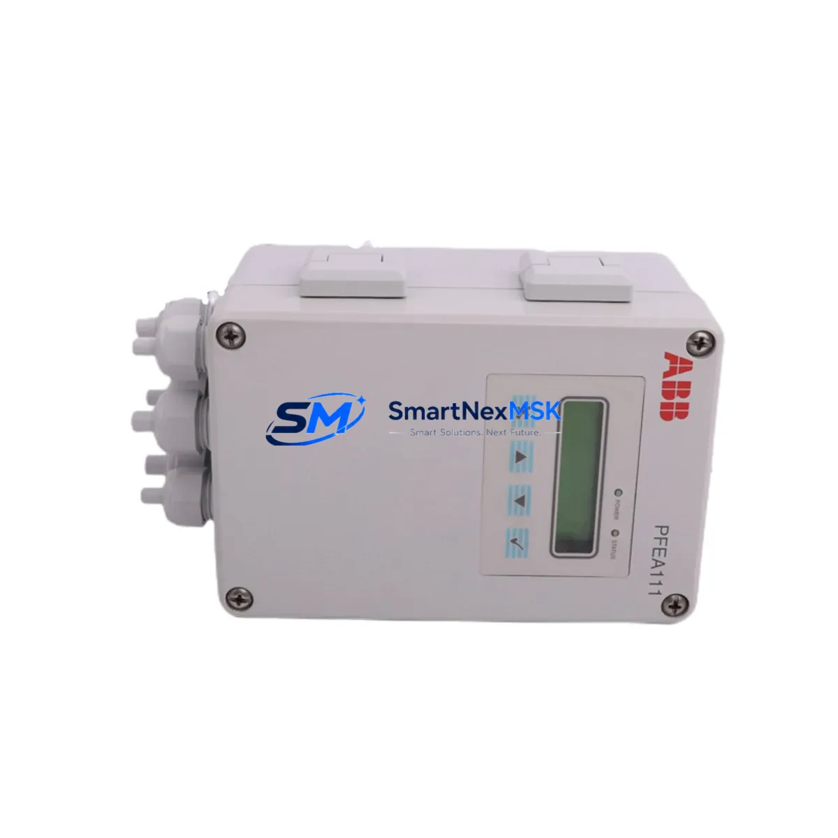
For maintenance engineers managing paper mills, metal processing lines, printing presses, and textile production systems, the PFEA112-65 addresses one of the most common upgrade challenges: replacing a discontinued tension amplifier without disrupting the broader control architecture. The module accepts load cell signals from standard tension roll transducers and conditions them into clean analog outputs compatible with ABB AC500 PLCs, ABB Freelance DCS controllers, and third-party SCADA systems. Its 65 mA output range and high-resolution signal processing make it a direct functional replacement for earlier PFEA110 and PFEA111 variants in most retrofit scenarios.
Upgrade Compatibility Table
| Parameter | Specification / Retrofit Note |
|---|---|
| Part Number | PFEA112-65 / 3BSE050091R65 |
| Brand | ABB |
| Series | PFEA (Tension Measurement & Amplifier Series) |
| Function | Tension Signal Amplifier — load cell input to analog output |
| Output Range | 65 mA (high-range variant) |
| Replaces | PFEA110, PFEA111, earlier 3BSE0xxxxx PFEA variants |
| Terminal Compatibility | Pin-compatible with standard PFEA DIN-rail mounting blocks |
| Communication | Analog signal output; compatible with ABB AC500 AI modules and Freelance I/O |
| Power Supply | 24 VDC nominal; verify PSU capacity before installation |
| Installation Environment | Control cabinet, DIN-rail mount, IP20 enclosure |
| Commissioning | Zero/span calibration via front-panel potentiometers; no special tools required |
| Origin | Germany |
| Weight | 2,050 g (packaged) |
| Warranty | 12-Month Warranty — tested before shipment |
Retrofit Planning for Existing Automation Systems
A successful PFEA112-65 retrofit begins well before the module arrives on site. Maintenance and procurement engineers should conduct a full control cabinet audit to map every component in the tension measurement loop. In a typical PFEA-based tension control system, the signal chain runs from load cell transducers mounted on tension rolls, through the PFEA112-65 amplifier, into an ABB AC500 analog input module (such as the AI523 or AI531), and then to the PLC logic executing the tension regulation algorithm.
Before removing the old amplifier, document the existing terminal wiring using the original PFEA wiring diagram. The PFEA112-65 uses a standard screw-terminal DIN-rail block, and in most installations the field wiring can be transferred directly without re-labeling. However, engineers should verify the 24 VDC power supply rail capacity — particularly in cabinets where a SITOP PSU or ABB CP-E power supply is shared across multiple signal conditioning modules. Adding or replacing a PFEA amplifier may marginally increase current draw, and an undersized PSU can introduce signal noise or cause intermittent faults.
The analog output from the PFEA112-65 feeds directly into the PLC’s AI channel. If the existing program uses scaled engineering units (e.g., Newtons or kg-force), confirm that the new module’s zero and span calibration matches the original before going live. In ABB AC500 systems programmed with Automation Builder, this typically means checking the AI channel scaling block in the PLC program — no code changes are needed if the output signal range is identical. For systems using ABB Freelance DCS with PROFIBUS DP communication, also verify that the DP node address and GSD file remain unchanged after the swap.
In cabinets where the PFEA112-65 sits alongside ABB NTAI05 analog input termination units, ABB NDIO-01 digital I/O modules, or Phoenix Contact MINI MCR signal isolators, engineers should inspect all neighboring terminal blocks and cable shields for signs of corrosion or loose connections — a common root cause of tension measurement drift in aging systems. Replacing the amplifier is also an ideal time to check the condition of the load cell excitation wiring and any inline fuse holders protecting the sensor circuit.
For systems with an ABB CP600 or CP400 HMI displaying live tension values, no HMI screen modifications are required as long as the analog signal scaling is preserved. The operator interface will continue to display tension readings without interruption once the new module is calibrated and the PLC is returned to RUN mode.
Downtime Control During System Migration
Minimizing production downtime during a PFEA112-65 swap requires a structured hot-swap protocol. Begin by placing the PLC in manual mode or activating a tension bypass interlock if the control system supports it — this prevents the tension regulation loop from generating fault outputs during the module exchange. In continuous process lines such as paper machines or slitter-rewinders, coordinate the swap with a scheduled roll change or splice event to avoid unplanned stops.
With the cabinet de-energized and LOTO procedures applied, remove the old PFEA amplifier from its DIN-rail mounting block. Transfer the field wiring terminal by terminal, using the documented wiring map. Seat the PFEA112-65 onto the rail, re-energize the 24 VDC supply, and perform zero calibration with no load on the tension roll. Apply a known reference load (or use the mechanical span adjustment) to set the full-scale output. Once calibration is confirmed, return the PLC to AUTO mode and monitor the tension feedback signal for at least one full production cycle before signing off.
Because the PFEA112-65 is a direct wiring-compatible replacement for earlier PFEA variants, the entire swap — including calibration — can typically be completed within 30 to 60 minutes by a qualified maintenance technician. Keeping a spare PFEA112-65 in the site’s critical spare parts inventory eliminates the risk of extended downtime caused by procurement lead times for this discontinued module family.
Retrofit Support FAQ
Q1: Is the PFEA112-65 a direct drop-in replacement for the PFEA110 and PFEA111?
In most installations, yes. The PFEA112-65 uses the same DIN-rail mounting block and terminal layout as earlier PFEA variants. The primary difference is the output current range (65 mA for the -65 suffix). Verify that your downstream AI module and PLC scaling are configured for this range before installation.
Q2: Does replacing the PFEA112-65 require changes to the PLC program or HMI?
No program or HMI changes are required if the replacement module is calibrated to the same zero and span as the original. The PLC sees an identical analog signal, and HMI displays continue to function without modification.
Q3: How is the PFEA112-65 tested before shipment?
Each unit undergoes functional power-on testing and signal output verification prior to dispatch. Units are shipped with protective packaging to prevent transit damage. A 12-month warranty covers all defects in materials and workmanship from the date of delivery.
Q4: Can you supply the PFEA112-65 for long-term or multi-site inventory programs?
Yes. SMARTNEXMSK maintains stock of the PFEA112-65 3BSE050091R65 and can support blanket orders, scheduled releases, and multi-site spare parts programs. Contact our team to discuss volume pricing and lead time commitments.
© 2026 SMARTNEXMSK. All rights reserved.
Original Source: https://smartnexmsk.com
Contact: sales@smartnexmsk.com | +86 18259474341


