ABB PFSK142 3BSE006505R1 Retrofit-Ready S100 Bus Interface for Advant OCS Control Systems
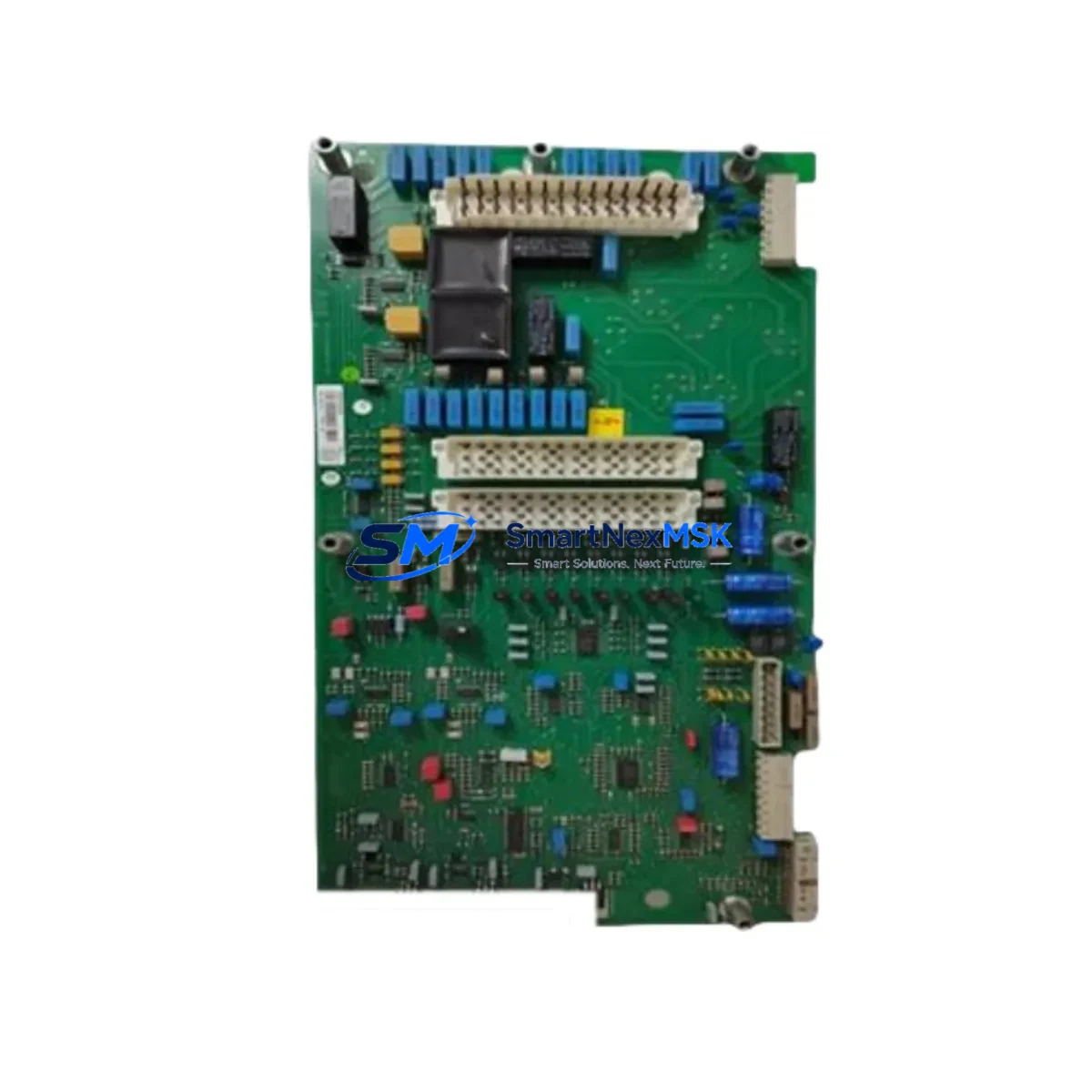
The ABB PFSK142 (part number 3BSE006505R1) is a high-reliability S100 Bus Communication Interface module designed for the ABB Advant OCS distributed control system platform. As legacy Advant OCS installations continue to operate across petrochemical, power generation, pulp and paper, and heavy manufacturing facilities worldwide, the PFSK142 remains one of the most critical retrofit components for engineers tasked with extending system life, replacing failed boards, or executing a phased migration to modern ABB 800xA or AC500 control architectures.
SMARTNEXMSK maintains verified inventory of the PFSK142 3BSE006505R1, sourced from decommissioned systems and authorized surplus channels. Every unit undergoes functional testing prior to shipment and is covered by a 12-month warranty against manufacturing defects and operational failure.
Upgrade Compatibility Table
| Parameter | PFSK142 3BSE006505R1 | Retrofit Notes |
|---|---|---|
| Bus Interface | S100 I/O Bus | Direct replacement for existing S100 backplane slots |
| Mounting | Standard Advant OCS subrack (S100 rack) | No mechanical modification required |
| Communication Protocol | Proprietary ABB S100 serial bus | Compatible with PFSK130, PFSK150 series controllers |
| Power Supply | 24 VDC via backplane | Verify PSSR021 or PSSR022 PSU capacity before swap |
| Replacement Compatibility | Direct drop-in for PFSK142 variants | Confirm firmware revision with site engineer |
| Commissioning | Address set via DIP switch on board | Match original module address; no software re-addressing needed |
| Warranty | 12 Months | Covered from date of shipment; includes functional test certificate |
Retrofit Planning for Existing Automation Systems
Replacing a PFSK142 in an active Advant OCS system requires careful pre-work to avoid unplanned shutdowns. Before pulling the failed module, engineers should document the existing DIP switch address settings and verify that the replacement unit is configured identically. The S100 bus topology in a typical Advant OCS cabinet connects the PFSK142 to the main processor module — commonly a PFSK101 or PFSK102 CPU board — through a dedicated backplane slot in the S100 subrack.
Power budget verification is essential. The PSSR021 24 VDC power supply module or its successor PSSR022 must have sufficient headroom to support the replacement PFSK142 alongside co-installed modules such as the PFSK130 analog input board, PFSK140 digital output module, and any PFSK160 pulse counter cards occupying adjacent slots. Overloaded power rails are a common cause of intermittent communication faults that are often misdiagnosed as bus interface failures.
Terminal wiring on the S100 field bus connector should be photographed and labeled before disconnection. In older installations, the PFSK142 may share a communication segment with PFSK112 or PFSK113 serial interface modules that handle Modbus RTU or PROFIBUS DP bridging to field instruments. Disrupting these links without a documented recovery plan can cascade into loss of visibility across multiple control loops.
For sites running ABB Master software on the engineering workstation, the module replacement does not require a database download in most cases — the PFSK142 is recognized automatically by the S100 bus scanner on power-up. However, if the site has migrated the HMI layer to an ABB 800xA OPC server or a third-party SCADA platform, the OPC tag mapping should be validated after the swap to confirm that all process values are updating correctly.
Where the retrofit scope extends beyond a single board replacement — for example, when upgrading an entire S100 subrack to a modern AC500 PLC platform — the PFSK142 is typically the last module to be decommissioned, as it maintains the communication bridge between legacy field I/O and the new controller during the parallel-run commissioning phase. In these projects, a TB820V2 ModuleBus modem or a CI854 PROFIBUS DP interface module on the new 800xA system is configured to mirror the S100 data before the cutover.
Downtime Control During System Migration
Minimizing unplanned downtime during a PFSK142 replacement is achievable with the right preparation. The recommended approach is a hot-standby swap during a scheduled maintenance window: with the process held at a stable setpoint, the failed module is removed and the tested replacement is inserted into the same backplane slot. Because the PFSK142 does not store process data locally, the S100 bus re-initializes within seconds of power restoration, and the CPU module resumes normal scan cycles without requiring a cold restart.
For sites where even a brief interruption is unacceptable — such as continuous chemical reactors or power plant auxiliary systems — a shadow rack strategy is recommended. A spare S100 subrack pre-loaded with a configured PFSK142, PFSK130 input cards, and PFSK140 output cards is staged adjacent to the live cabinet. The cutover is executed by switching the field wiring terminal blocks rather than the modules themselves, reducing the live interruption to under two minutes.
Original ladder logic and function block programs stored in the PFSK101 or PFSK102 CPU are unaffected by a PFSK142 swap, provided the module address is matched correctly. Engineers should retain a backup of the Master application database on the programming terminal before any hardware change, as a precaution against unexpected CPU resets during the bus re-scan sequence.
Retrofit Support FAQ
Q: Is the PFSK142 3BSE006505R1 a direct drop-in replacement for all PFSK142 variants?
A: In most cases, yes. The 3BSE006505R1 is the standard catalog revision of the PFSK142 and is compatible with all standard S100 subracks. If your installation uses an early-revision PFSK142 with a different firmware label, contact our technical team to confirm cross-compatibility before ordering.
Q: What commissioning steps are required after installing the replacement module?
A: Set the DIP switches on the PFSK142 to match the original module address. Re-seat the module in the backplane, restore power, and observe the S100 bus status LEDs. The CPU should recognize the module within one scan cycle. Validate all associated I/O points from the HMI or engineering workstation before returning the loop to automatic control.
Q: Can the PFSK142 be used in a system that has been partially upgraded to PROFIBUS DP or Modbus TCP?
A: Yes. The PFSK142 operates on the S100 bus layer independently of higher-level communication protocols. It can coexist with PFSK112 Modbus RTU interface modules and CI840 PROFIBUS DP adapters in the same cabinet, provided the S100 bus address space is managed correctly and no address conflicts exist.
Q: What does the 12-month warranty cover?
A: All PFSK142 3BSE006505R1 units shipped by SMARTNEXMSK are covered for 12 months from the date of shipment against functional failure under normal operating conditions. Each unit is tested prior to dispatch and ships with a functional test record. In the event of a warranty claim, we provide a replacement unit or full refund at our discretion.
© 2026 SMARTNEXMSK. All rights reserved.
Original Source: https://smartnexmsk.com
Contact: sales@smartnexmsk.com | +86 18259474341


