ABB PL810 Maintenance-Ready Spare for AC500 Automation
The ABB PL810 Power Link Module is a critical communication and power distribution component within the ABB AC500 PLC platform — one of the most widely deployed programmable logic controller families in industrial automation, process control, and infrastructure applications worldwide. When this module fails or degrades, the consequences extend beyond a single I/O channel: the entire AC500 backplane communication chain can be disrupted, triggering unplanned shutdowns, production losses, and extended maintenance windows. Stocking a verified replacement PL810 is not optional for facilities running continuous or semi-continuous processes — it is a fundamental element of any responsible spare parts strategy.
This listing provides an original ABB PL810 module, sourced from authorized supply channels, individually tested prior to shipment, and backed by a 12-month warranty. Each unit is verified for firmware compatibility and physical integrity before dispatch, ensuring that your maintenance team can install and commission the replacement with confidence — minimizing the gap between fault detection and system restoration.
Spare Maintenance Table
| Parameter | Specification / Detail |
|---|---|
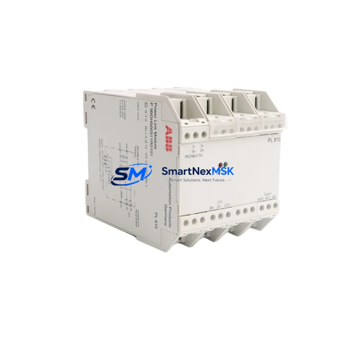
| Part Number / SKU | PL810 |
| Full Description | ABB PL810 Power Link Module |
| Compatible Platform | ABB AC500 PLC Series |
| Module Function | Power Link communication interface for AC500 I/O expansion |
| Communication Interface | Power Link (POWERLINK / EPL) fieldbus |
| Supply Voltage | 24 V DC (nominal), per AC500 system specification |
| Mounting | DIN rail, AC500 backplane slot |
| Operating Temperature | 0 °C to +60 °C (standard industrial environment) |
| Protection Class | IP20 (control cabinet installation) |
| Country of Origin | Germany |
| Condition | Original, new or tested-serviceable |
| Pre-shipment Test | Yes — functional and communication verification |
| Warranty | 12 Months from date of shipment |
| Typical Application | Factory automation, process control, infrastructure PLC systems |
| Maintenance Recommendation | Inspect annually; replace on communication fault or backplane error codes |
Maintenance Planning for Continuous Operation
Replacing the PL810 in an AC500 system is rarely an isolated task. Experienced maintenance engineers know that a Power Link communication fault often signals stress across adjacent components in the same control cabinet. A disciplined site inspection during a PL810 replacement should include the following checks and, where appropriate, proactive spare stocking:
Begin with the AC500 CPU module (such as the PM573, PM583, or PM595 series) — verify that firmware is current and that no latent communication errors are logged. The PL810 interfaces directly with the CPU’s Power Link port, and a degraded CPU communication stack can cause repeated module faults even after a PL810 swap. Next, inspect the AC500 I/O terminal units (TU515, TU516, TU531 series) seated on the same backplane: loose or corroded contacts on terminal units are a common secondary cause of Power Link instability.
Check the 24 V DC power supply module feeding the AC500 rack — voltage ripple or marginal current capacity accelerates module wear. If the cabinet uses an ABB CP600 or CP400 HMI panel connected via Ethernet or serial to the AC500 CPU, verify that the HMI communication parameters remain intact after the PL810 replacement, as a CPU restart may reset communication settings. For systems using PROFIBUS DP or Modbus RTU communication modules (CM572-DP, CM575-DN), confirm that network addresses and baud rates are preserved in the CPU project backup before powering down.
Inspect signal isolators and surge protection devices on analog I/O channels — particularly on 4–20 mA loops connected to SM560 or SM500 series analog I/O modules. A power event that damages the PL810 may also have stressed isolation barriers. Review fuse holders and miniature circuit breakers in the 24 V DC distribution rail; replace any that show signs of thermal discoloration. Finally, check terminal blocks and cable ferrules on the Power Link RJ45 or fiber connections for mechanical damage, and confirm that grounding and shielding of the communication cable meets ABB AC500 installation guidelines to prevent future EMI-induced faults.
Site Replacement Workflow
A structured replacement workflow reduces downtime and prevents secondary faults during the PL810 swap:
1. Pre-replacement preparation: Download and archive the current AC500 CPU project using ABB Automation Builder or PS501 Control Builder Plus. Record all Power Link node addresses, I/O module configurations, and network parameters. Confirm that the replacement PL810 carries the same hardware revision as the installed unit, or verify ABB’s compatibility matrix for cross-revision substitution.
2. Safe isolation: Follow your site’s lockout/tagout (LOTO) procedure. De-energize the 24 V DC supply to the AC500 rack. Disconnect the Power Link cable before removing the module to avoid backplane damage.
3. Module exchange: Remove the faulty PL810 by releasing the DIN rail latch. Seat the replacement module firmly until the backplane connector engages. Reconnect the Power Link cable and restore 24 V DC power.
4. Commissioning verification: Power up the AC500 system and observe the PL810 status LEDs. Confirm that all I/O nodes appear online in the CPU diagnostic view. Run a short functional test of connected field devices before returning the system to production. Log the replacement in your maintenance management system (CMMS) and update the spare parts inventory accordingly.
This workflow is applicable whether you are replacing a failed module in an emergency shutdown scenario or performing a planned swap during a scheduled maintenance window. The PL810’s plug-and-play architecture within the AC500 platform means that — with a valid CPU project backup — commissioning time is typically under 30 minutes for a trained technician.
Spare Parts Support FAQ
Q1: Is this PL810 compatible with all AC500 CPU generations?
The PL810 is designed for the ABB AC500 V2 and V3 platform generations. Compatibility with specific CPU modules (PM573, PM583, PM591, PM595) depends on hardware revision and firmware version. We recommend confirming the hardware revision of your installed unit before ordering. Our technical team can assist with compatibility verification based on your CPU part number and project version.
Q2: What does the 12-month warranty cover?
The 12-month warranty covers manufacturing defects and functional failures under normal operating conditions as specified by ABB. Each unit is tested prior to shipment for communication functionality and physical integrity. Warranty claims are supported by our after-sales team; failed units within the warranty period are replaced or refunded subject to inspection.
Q3: How quickly can the PL810 be shipped, and what documentation is provided?
In-stock units are dispatched within 1–3 business days. Each shipment includes a packing list and, where available, original ABB documentation or a test report. Express shipping options are available for emergency maintenance situations. Contact our sales team for lead time confirmation on your specific order.
Q4: Can I use this module to replace an older or discontinued PL810 variant?
In most cases, yes — the PL810 form factor and backplane interface have remained consistent across AC500 production runs. However, if your existing installation uses a very early hardware revision, we recommend requesting a revision-matched unit or consulting ABB’s spare parts cross-reference guide. We maintain stock of multiple hardware revisions where available and can advise on the best substitution path for your system.
© 2026 SMARTNEXMSK. All rights reserved.
Original Source: https://smartnexmsk.com
Contact: sales@smartnexmsk.com | +86 18259474341


