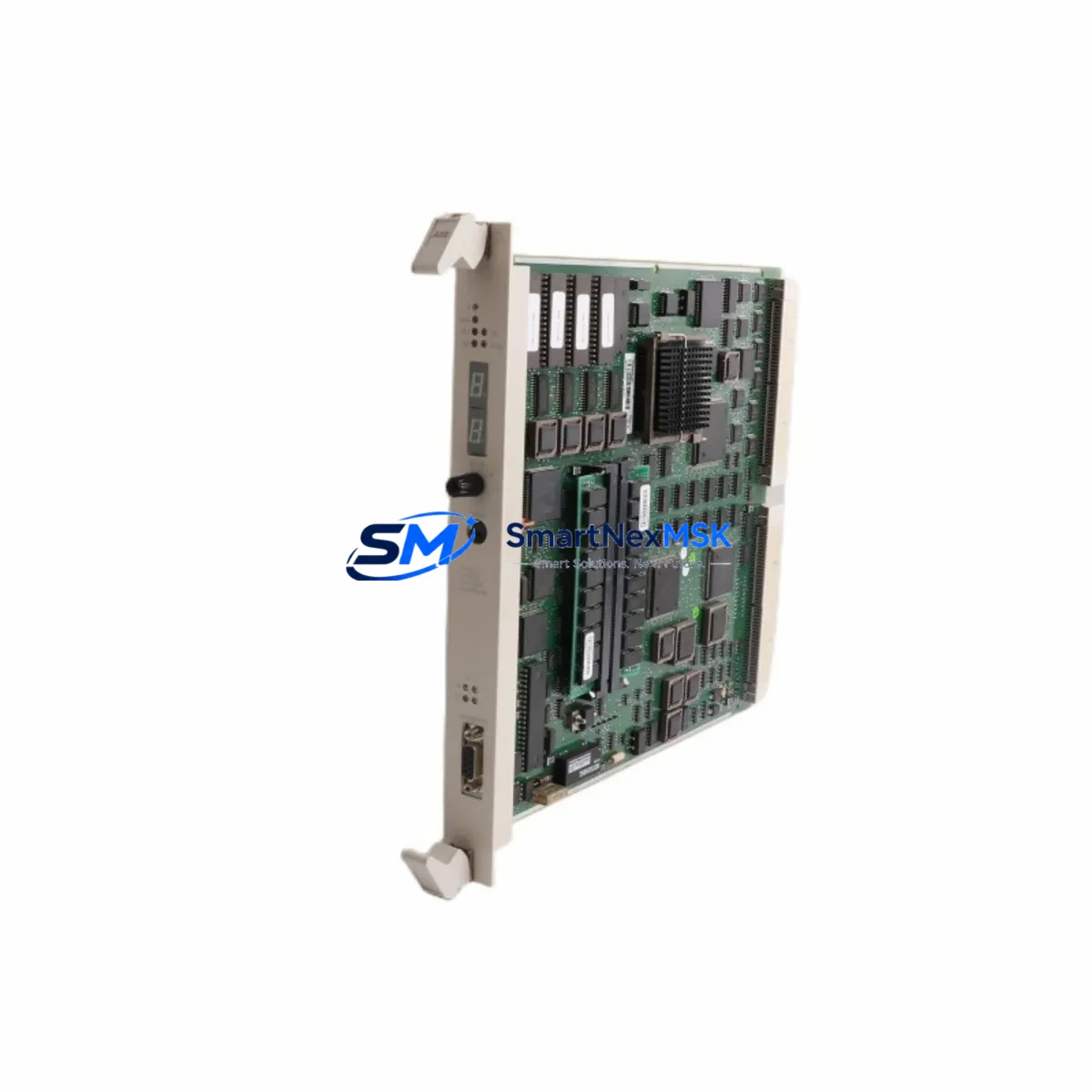
ABB PM510V08 3BSE008373R1 Retrofit-Ready CPU for AC500 Control Systems
The ABB PM510V08 (catalog number 3BSE008373R1) is a mid-range CPU module designed for the AC500 programmable logic controller platform. As legacy AC500 installations approach end-of-service milestones, the PM510V08 has become a primary retrofit target for engineers modernizing aging control cabinets, replacing discontinued PM503 and PM510V06 variants, and restoring production continuity on lines where spare parts are no longer available through standard distribution channels. With 512 KB program memory, onboard Modbus RTU/ASCII and PROFIBUS DP master/slave capability, and compatibility with the standard TB511 and TB521 terminal base units, the PM510V08 integrates into existing AC500 racks without mechanical modification.
This module ships fully tested, serialized, and covered by a 12-month warranty from date of invoice. Each unit undergoes functional verification against ABB AC500 firmware baseline prior to dispatch, ensuring the module initializes correctly on the target rack and communicates with connected I/O and HMI devices before it leaves our facility.
Upgrade Compatibility Table
| Parameter | PM510V08 3BSE008373R1 | Retrofit Notes |
|---|---|---|
| Terminal Base | TB511 / TB521 | Direct fit; no adapter required for standard AC500 racks |
| Backplane Interface | AC500 internal bus (K-Bus) | Compatible with all standard AC500 expansion modules |
| Communication Ports | COM1 (RS-232/RS-485), COM2 (RS-485) | Retains Modbus RTU/ASCII; verify baud rate settings in existing program |
| PROFIBUS DP | Master & Slave (onboard) | GSD file may need re-import if replacing PM503; station address preserved |
| Program Memory | 512 KB | Sufficient for most mid-scale AC500 applications; verify against existing project size |
| Power Supply Requirement | 24 VDC via terminal base | Confirm PS501 or PS502 power supply capacity before hot-swap |
| Firmware Compatibility | AC500 V2.x / V3.x | Confirm Control Builder Plus version matches target firmware |
| Replacement for | PM503, PM510V06, PM510V08 (earlier batches) | Pin-compatible; program reload required after swap |
| Installation Type | DIN rail / panel mount via TB base | No cabinet re-drilling required for standard AC500 enclosures |
| Warranty | 12 Months | Covers manufacturing defects; includes pre-shipment functional test report |
Retrofit Planning for Existing Automation Systems
A successful PM510V08 retrofit begins well before the module arrives on site. Engineers should pull the existing project archive from Control Builder Plus and verify the compiled program size against the 512 KB memory ceiling of the replacement CPU. In most AC500 mid-range installations, the program footprint sits comfortably below this threshold, but applications that have accumulated years of incremental logic additions — particularly those integrating DC532 digital combination I/O modules or AX522 analog I/O modules — should be audited for redundant function blocks before the swap.
Terminal wiring on the TB511 terminal base does not need to be disturbed during a CPU swap, which is one of the key advantages of the AC500 architecture. Field wiring connected to DA501 digital input modules and DA502 digital output modules remains in place; only the CPU module itself is extracted from the base. Before removal, document the current module address settings using the rotary switches on the front panel and photograph the LED status indicators to establish a pre-swap baseline.
For installations running PROFIBUS DP networks, the PM510V08’s onboard DP master port eliminates the need for a separate CI502-PNIO PROFINET or CI501-PNIO communication interface module in many retrofit scenarios, reducing rack slot consumption and simplifying the bill of materials. Where the existing system uses a CI504-PNIO for PROFINET connectivity, that module can remain in the rack alongside the new CPU without conflict.
Power budget verification is a mandatory pre-retrofit step. The PS501 power supply module feeding the AC500 rack must have sufficient headroom to support the PM510V08 alongside all installed I/O and communication modules. Calculate the total current draw from the rack’s module list and compare against the PS501’s rated output before proceeding. If the existing power supply is already operating near capacity — a common finding in older cabinets where I/O has been expanded incrementally — a PS502 power supply upgrade should be scoped into the retrofit plan.
HMI integration should be validated in the staging environment before field deployment. Panels running CP600 series HMI units connected via Modbus TCP or serial Modbus RTU will require a communication test after the CPU swap to confirm that variable addresses and data types have not shifted. If the original program used symbolic addressing throughout, this step is typically straightforward. Fixed-address programs require more careful verification against the HMI tag database.
Downtime Control During System Migration
Minimizing unplanned downtime during a CPU replacement is the primary operational concern for maintenance teams. The recommended approach for PM510V08 retrofits is a cold-swap with pre-staged backup: the replacement module is configured, firmware-matched, and program-loaded on a bench setup before the production line is taken offline. This reduces the live outage window to the time required for physical module exchange, terminal base re-seating, and a controlled restart sequence — typically 15 to 45 minutes for a prepared team.
Before initiating the swap, export the full project from Control Builder Plus including all POU source files, hardware configuration, and communication settings. Store this backup on at least two independent media. If the existing CPU is still partially functional, use the online monitoring view to capture current variable states and setpoint values that operators may have adjusted at the HMI — these runtime values are not always reflected in the saved project file and must be re-entered manually after the swap.
During the swap window, field devices connected to DA501 and DA502 I/O modules will lose their control outputs. Coordinate with the process team to place downstream equipment in a safe hold state before cutting power to the rack. After the PM510V08 is seated and power is restored, allow the CPU to complete its self-test sequence — indicated by the RUN LED transitioning from flashing to steady — before downloading the project. Verify all I/O module status LEDs are green before releasing the line to production.
For multi-rack systems where the PM510V08 acts as a master controller communicating with remote CI502-PNIO or CI504-PNIO interface modules over PROFINET, the network topology should be documented and the IP address assignments confirmed before the swap. PROFINET devices retain their configured IP addresses independently, so the new CPU will re-establish communication automatically once the project is downloaded and the network scan completes.
Retrofit Support FAQ
Q1: Is the PM510V08 3BSE008373R1 a direct drop-in replacement for the PM503 or PM510V06?
Yes. The PM510V08 is mechanically and electrically compatible with the TB511 and TB521 terminal bases used by earlier AC500 CPU variants. The existing terminal wiring does not need to be modified. However, the program must be re-downloaded after the swap, and any firmware-dependent function blocks should be verified against the PM510V08’s supported firmware version in Control Builder Plus before going live.
Q2: What pre-shipment testing is performed on each unit?
Every PM510V08 unit we supply undergoes a functional power-on test, communication port verification (COM1/COM2 and PROFIBUS DP), and firmware version confirmation prior to dispatch. A test record is available upon request. All units are covered by a 12-month warranty from the invoice date, covering manufacturing defects and functional failures under normal operating conditions.
Q3: How do I verify wiring compatibility before the swap?
The PM510V08 does not have direct field wiring — all I/O connections are made through the terminal base and expansion I/O modules. Confirm that your existing TB511 or TB521 base is in good condition and that the backplane connector shows no signs of corrosion or mechanical damage. Check that the 24 VDC supply to the terminal base is within the ±15% tolerance specified in the AC500 hardware manual before inserting the new CPU.
Q4: Can the PM510V08 communicate with third-party PROFIBUS devices already on the network?
Yes. The onboard PROFIBUS DP master port supports standard GSD-based device integration. If you are replacing a CPU that was previously configured as the DP master, import the existing GSD files into the new hardware configuration in Control Builder Plus and verify that the station addresses match the physical device settings. No changes to the field device wiring or termination resistors are required.
© 2026 SMARTNEXMSK. All rights reserved.
Original Source: https://smartnexmsk.com
Contact: sales@smartnexmsk.com | +86 18259474341


