ABB PM511V08 Retrofit-Ready CPU for AC500 Control Systems: Seamless Compatibility and Legacy System Upgrade
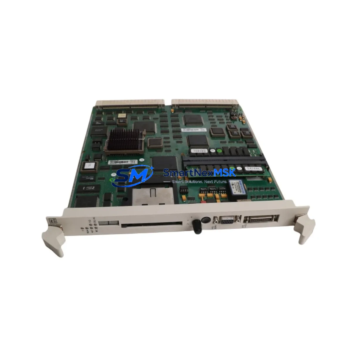
The ABB PM511V08 (part number 3BSE011180R1) is a high-performance CPU module designed for the ABB AC500 programmable logic controller platform. As industrial facilities face increasing pressure to modernize aging control infrastructure, the PM511V08 has become a critical component in retrofit projects targeting discontinued or end-of-life AC500 configurations. Whether you are replacing a failed PM503, PM510, or PM511 unit, or executing a planned upgrade from an older AC500 generation, the PM511V08 offers a reliable, specification-matched solution with minimal disruption to existing program logic and field wiring.
The PM511V08 supports the standard AC500 backplane architecture, allowing direct installation into existing TB511, TB521, or TB541 terminal base units without mechanical modification. Its onboard Ethernet port and support for CS31 and Modbus RTU communication protocols ensure continuity with legacy field devices, PROFIBUS DP networks, and HMI panels already deployed in the control cabinet. Engineers migrating from older CPU generations should verify the firmware revision level and confirm compatibility with the existing PS501 Control Builder Plus programming environment before commissioning.
When planning a retrofit using the PM511V08, the following verification steps are essential to ensure a smooth cutover and minimize unplanned downtime.
Upgrade Compatibility Table
| Parameter | Details |
|---|---|
| Compatible Terminal Bases | TB511, TB521, TB541 (standard AC500 backplane) |
| Replaces | PM503, PM510, PM511 (same form factor) |
| Communication Protocols | Ethernet (10/100 Mbps), CS31, Modbus RTU, CANopen (optional) |
| Programming Environment | PS501 Control Builder Plus V2.x and above |
| Power Supply Compatibility | AC500 standard 24 VDC system bus; verify PS501 or PS560 power module capacity |
| I/O Expansion | Supports SM500 series digital and analog I/O modules via local bus |
| HMI Compatibility | Compatible with CP600 and CP400 series operator panels via Ethernet or serial |
| Installation Requirement | DIN rail mount; no additional hardware required for same-generation swap |
| Retrofit Recommendation | Back up existing program and retain original TB unit; swap CPU only |
| Commissioning Note | Verify module address settings and I/O mapping after replacement |
| Warranty | 12 Months — covers manufacturing defects and functional failure under normal use |
Retrofit Planning for Existing Automation Systems
A successful PM511V08 retrofit begins well before the physical swap. Start by auditing the existing control cabinet to document the current CPU firmware version, the terminal base model, and the power budget of the installed PS501 or PS560 power supply module. In many legacy AC500 installations, the power module is shared across the CPU and multiple SM500 series I/O modules — including SM511F digital input, SM512F digital output, and SM532F analog I/O cards. Confirm that the total current draw remains within the power module’s rated output after the new CPU is installed.
Next, export and archive the full project from PS501 Control Builder Plus, including all POU (Program Organization Unit) files, variable declarations, and hardware configuration. If the existing system uses a TA521 or TA526 communication adapter for PROFIBUS DP or CANopen connectivity, verify that the adapter firmware is compatible with the PM511V08’s communication stack. Systems using a CI590-CS31-HA CS31 coupler for remote I/O expansion should also confirm that the coupler’s node address and baud rate settings are preserved during the CPU swap.
For facilities running CP600 series HMI panels, review all screen tags and communication driver settings. The PM511V08 communicates with CP600 panels via Ethernet using the ABB proprietary protocol; ensure the IP address assignment and subnet configuration in the HMI project match the new CPU’s network settings. If the plant uses a third-party SCADA system connected via Modbus TCP, update the register map documentation to reflect any address changes introduced during the upgrade.
Before the cutover, perform a bench test of the PM511V08 with a spare TB511 terminal base and a representative subset of SM500 I/O modules. Load the archived program, verify all I/O channel assignments, and simulate key control sequences. This pre-commissioning step is the most effective way to identify firmware incompatibilities or configuration errors before the module reaches the production floor.
Downtime Control During System Migration
Minimizing production downtime during a CPU replacement requires a structured cutover plan. Schedule the physical swap during a planned maintenance window and prepare a rollback procedure in case the new module does not initialize correctly. Keep the original PM511 or PM510 CPU on hand as a fallback unit, and retain a copy of the last known-good program backup on a dedicated engineering laptop running PS501 Control Builder Plus.
During the swap, power down the AC500 rack in the correct sequence: disable field outputs first, then shut down the CPU, and finally remove power from the PS501 or PS560 supply. Install the PM511V08 into the existing TB terminal base, restore power, and allow the module to complete its self-diagnostic cycle before downloading the program. Use the Control Builder Plus online monitoring function to verify that all I/O channels are reporting correctly before releasing the system to production. Document the commissioning date, firmware version, and any configuration changes in the plant’s maintenance log to support future audits and warranty claims.
Retrofit Support FAQ
Q1: Is the PM511V08 a direct drop-in replacement for the PM510 or PM503?
Yes. The PM511V08 uses the same TB-series terminal base footprint as the PM510 and PM503. In most cases, the existing terminal base, field wiring, and I/O modules can be retained without modification. A program re-download and I/O verification are required after the swap.
Q2: What commissioning steps are required after installation?
After installing the PM511V08, download the archived program via PS501 Control Builder Plus, verify the hardware configuration matches the installed I/O modules, check all communication link statuses (Ethernet, CS31, Modbus), and confirm that HMI tags and SCADA register mappings are functioning correctly before returning the system to automatic mode.
Q3: How is wiring compatibility handled during the retrofit?
The PM511V08 connects to field wiring through the existing TB terminal base. No rewiring of field cables is required for a same-generation CPU swap. If upgrading from a significantly older AC500 generation, verify that the terminal base model is compatible and that the I/O module slot assignments match the original hardware configuration.
Q4: What does the 12-month warranty cover?
All PM511V08 units supplied by SMARTNEXMSK carry a 12-month warranty covering manufacturing defects and functional failure under normal operating conditions. Each unit undergoes functional testing prior to shipment. Warranty claims are supported by our technical team; contact sales@smartnexmsk.com with your order reference and a description of the fault.
© 2026 SMARTNEXMSK. All rights reserved.
Original Source: https://smartnexmsk.com
Contact: sales@smartnexmsk.com | +86 18259474341


