ABB PM511V16 3BSE011181R1 Maintenance-Ready Spare for AC500 Automation
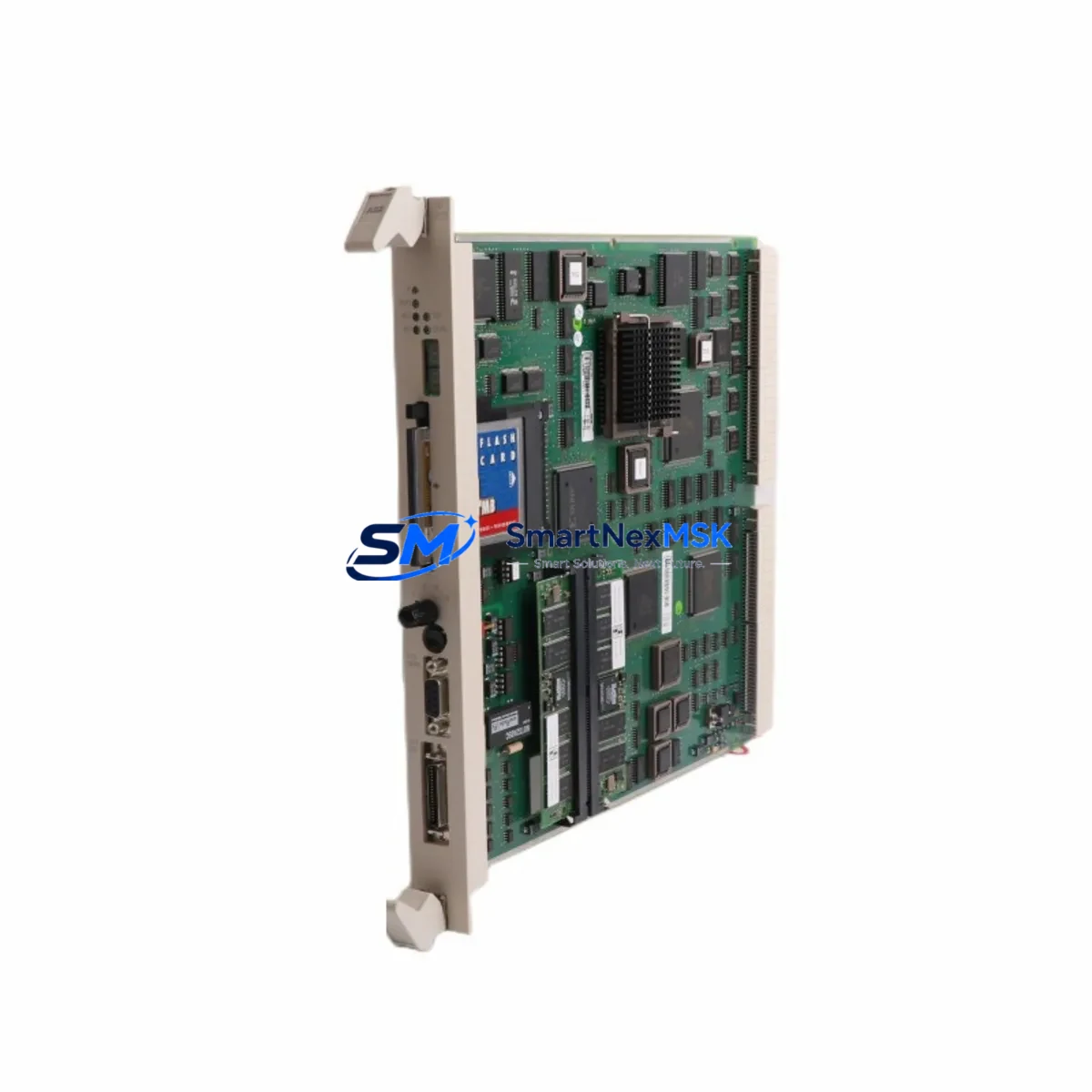
The ABB PM511V16 (part number 3BSE011181R1) is a central processing unit module within ABB’s AC500 programmable logic controller platform — one of the most widely deployed industrial automation architectures in process control, power distribution, and manufacturing environments worldwide. For maintenance engineers managing aging AC500 installations, securing a verified, original PM511V16 spare is a critical step in any downtime-reduction strategy. This listing provides a tested, original PM511V16 unit with 16 MB program memory, full AC500 backplane compatibility, and a 12-month warranty, ready for immediate site deployment.
Whether you are responding to an unplanned CPU fault, executing a scheduled control cabinet overhaul, or building a strategic spare parts buffer for a multi-line facility, the PM511V16 delivers the reliability and compatibility that industrial maintenance teams depend on. Each unit is inspected, function-tested, and shipped with protective packaging to ensure it arrives in field-ready condition.
Spare Maintenance Table
| Parameter | Specification |
|---|---|
| Part Number | 3BSE011181R1 |
| Model | PM511V16 |
| Brand | ABB |
| Series | AC500 |
| Module Type | PLC CPU Module |
| Program Memory | 16 MB |
| Communication Interfaces | Ethernet, serial (CS31 bus compatible) |
| Backplane Compatibility | AC500 TB511, TB521, TB541 terminal bases |
| Operating Voltage | 24 V DC (via terminal base) |
| Operating Temperature | 0 °C to +60 °C |
| Protection Rating | IP20 |
| Origin | Germany |
| Condition | Original, tested before shipment |
| Compatibility | AC500 V2 / V3 system architecture |
| Installation | DIN rail via AC500 terminal base |
| Warranty | 12 months from date of shipment |
| Application Environment | Industrial automation, process control, power distribution |
Maintenance Planning for Continuous Operation
When a PM511V16 CPU fault is identified during routine control cabinet inspection or triggered by a system alarm, the replacement process rarely involves the CPU alone. Experienced maintenance engineers know that a CPU failure event is an opportunity to audit the entire AC500 rack and associated electrical circuit for latent faults that could cause the next unplanned outage.
Begin by verifying the AC500 power supply module (such as the PS501 or PS502 series) — an undersized or aging power supply is a common root cause of intermittent CPU resets and memory corruption. Inspect the TB511 or TB521 terminal base on which the PM511V16 is seated; worn connector contacts or cracked housings can cause unreliable module seating and communication errors. Check all SM500 series digital and analog I/O modules installed in the same rack — a shorted I/O channel can place abnormal load on the backplane bus and stress the CPU.
For systems using fieldbus communication, inspect the CM572-DP PROFIBUS master module or CM589-PNIO PROFINET interface module for firmware version compatibility with the replacement PM511V16. Mismatched firmware between the CPU and communication modules is a frequent source of post-replacement startup failures. If the installation includes CI590-CS31-HA CS31 bus couplers, verify that the bus termination resistors are correctly installed and that cable shielding is intact.
On the power distribution side, inspect the 24 V DC panel power supply feeding the AC500 rack — measure output voltage under load and check for ripple that could affect CPU stability. Review the circuit breaker and fuse protection upstream of the PLC cabinet; a nuisance trip that caused the original CPU fault may recur if the protection device is not also serviced. If the system includes signal isolators or loop-powered transmitters on analog input channels, verify their output ranges are within the SM500 analog module’s configured input span to prevent scaling errors after CPU replacement.
For facilities running CP600 or CP620 HMI panels connected to the AC500 via Ethernet or serial link, confirm that the HMI project’s PLC communication settings (IP address, rack/slot addressing) match the replacement CPU’s configuration before restarting the system. A brief HMI communication test before full production restart can prevent operator confusion and false alarms during the recovery phase.
Building a structured spare parts inventory that includes the PM511V16 alongside complementary AC500 components — power supplies, I/O modules, terminal bases, and communication modules — is the most effective strategy for minimizing mean time to repair (MTTR) across your AC500 installations.
Site Replacement Workflow
Replacing the PM511V16 in a live AC500 installation follows a structured sequence designed to minimize downtime and eliminate configuration errors:
1. Pre-replacement preparation: Back up the existing CPU program and configuration using ABB Automation Builder software. Record the current IP address, subnet mask, gateway, and any fieldbus node addresses configured on the outgoing module. Photograph the wiring and module arrangement in the cabinet for reference.
2. Safe isolation: Follow your site’s lockout/tagout (LOTO) procedure. De-energize the AC500 rack via the upstream circuit breaker. Confirm zero voltage at the terminal base power input before proceeding.
3. Module removal and installation: Release the PM511V16 from the terminal base by pressing the release lever and sliding the module upward. Insert the replacement PM511V16 into the same terminal base slot, ensuring the module seats fully and the locking lever engages. Do not force the module — misalignment can damage the backplane connector.
4. Configuration restore: Re-energize the rack and connect a programming laptop via Ethernet. Download the backed-up program and configuration to the new CPU using Automation Builder. Verify that all I/O module addresses, fieldbus parameters, and communication settings are correctly restored.
5. Functional verification: Perform a controlled I/O test — cycle each digital output, verify analog input readings, and confirm fieldbus communication status on all connected nodes. Check HMI communication and confirm that all process values are displayed correctly before returning the system to automatic operation.
This workflow is applicable whether you are replacing a failed PM511V16 on an emergency basis or performing a planned swap as part of a preventive maintenance schedule. The same procedure applies when upgrading from an earlier AC500 CPU variant, provided the replacement module’s firmware is compatible with the installed I/O and communication modules.
Spare Parts Support FAQ
Q1: Is the PM511V16 (3BSE011181R1) compatible with both AC500 V2 and V3 system architectures?
The PM511V16 is designed for the AC500 platform and is compatible with AC500 V2 system configurations. For AC500 V3 installations, compatibility depends on the specific terminal base and I/O module versions in use. We recommend confirming your system’s hardware generation before ordering. Our technical team can assist with compatibility verification based on your existing rack configuration.
Q2: What testing is performed before shipment?
Each PM511V16 unit undergoes functional power-on testing and communication interface verification before dispatch. Units that do not pass testing are not listed for sale. The 12-month warranty covers manufacturing defects and functional failures under normal operating conditions from the date of shipment.
Q3: How should the PM511V16 be stored if it is purchased as a long-term spare?
Store the module in its original anti-static packaging in a dry environment between -25 °C and +70 °C with relative humidity below 95% (non-condensing). Avoid storage near strong electromagnetic fields or corrosive atmospheres. Inspect the module annually and perform a power-on test every 24 months to confirm readiness for deployment.
Q4: Can you supply multiple PM511V16 units for a fleet-wide spare parts program?
Yes. We support bulk spare parts procurement for facilities managing multiple AC500 installations. Volume pricing, consolidated shipping, and staggered delivery schedules are available. Contact our sales team to discuss your inventory requirements and lead time expectations.
© 2026 SMARTNEXMSK. All rights reserved.
Original Source: https://smartnexmsk.com
Contact: sales@smartnexmsk.com | +86 18259474341


