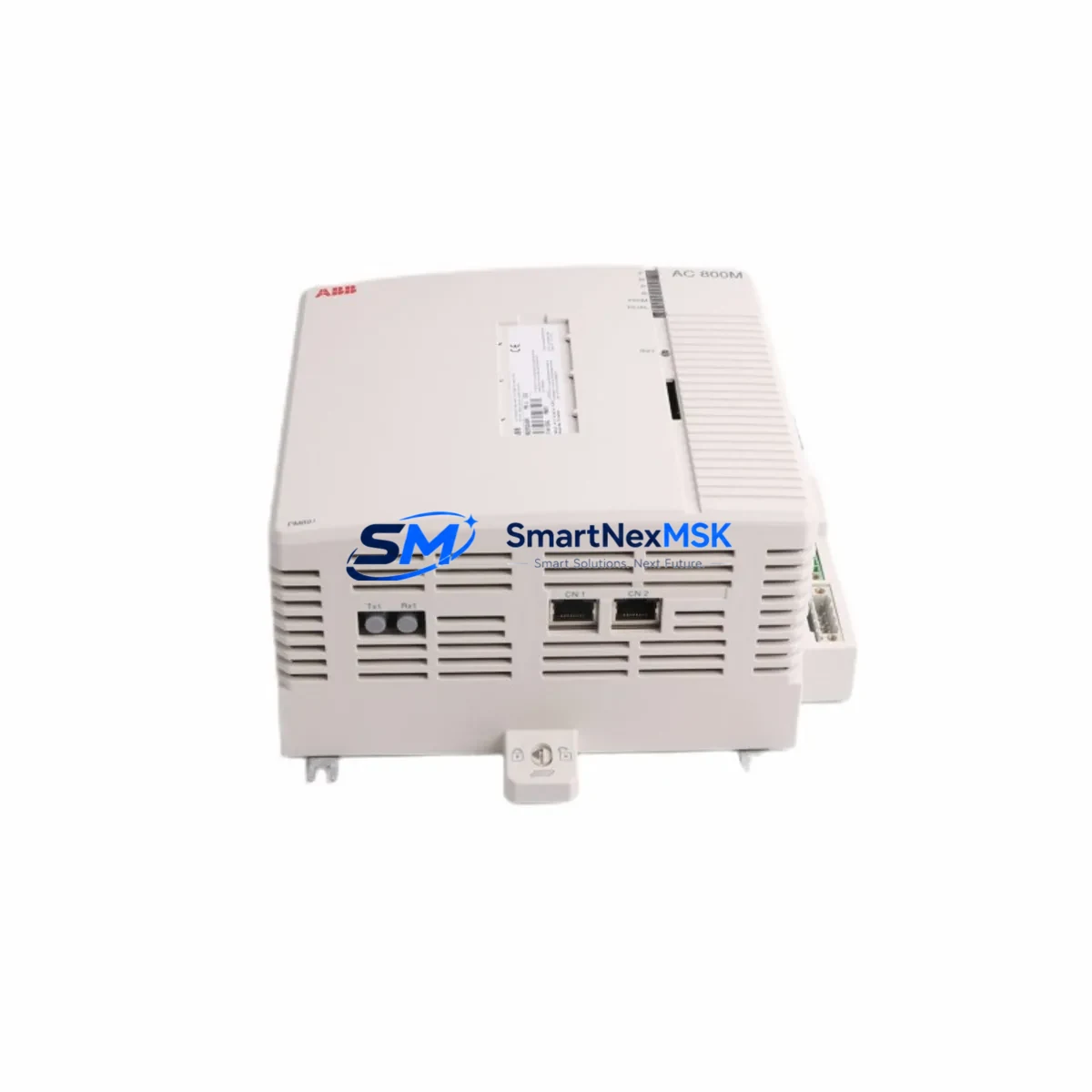
ABB PM891K01 36BSE053241R1 Retrofit-Ready CPU for AC800M Control Systems
The ABB PM891K01 (catalog reference 36BSE053241R1) is a high-performance central processing unit designed for the AC800M distributed control platform — one of ABB’s most widely deployed process automation architectures in oil & gas, power generation, pulp & paper, and chemical processing industries. As legacy AC800M installations age and original CPU modules reach end-of-life, the PM891K01 serves as the definitive retrofit-ready replacement, offering full backward compatibility with existing backplane wiring, I/O configurations, and application programs developed in ABB Control Builder M.
Whether you are replacing a failed PM860K01 or PM865K01 in a running production line, upgrading from an earlier AC800M generation to extend system life by 10–15 years, or consolidating redundant controller pairs to reduce spare-parts inventory, the PM891K01 delivers the processing headroom and communication flexibility required for modern process control demands. Its dual-port Ethernet backbone supports both MMS/IEC 61850 and OPC UA connectivity, enabling seamless integration with SCADA layers, historian servers, and plant-wide data infrastructure without requiring changes to field wiring or PLC rack layout.
Upgrade Compatibility Table
| Parameter | PM891K01 (This Unit) | Typical Legacy Units (PM860 / PM865) |
|---|---|---|
| Backplane Interface | AC800M Standard Rack (TB807 / TB840) | Same — direct slot-for-slot replacement |
| Communication Ports | 2× Ethernet (CEX-Bus), 1× RS-232 service port | 1× Ethernet (PM860) / 2× Ethernet (PM865) |
| Profibus DP Support | Via CI854 / CI854A Profibus Master module | Compatible — same CI854 module retained |
| FOUNDATION Fieldbus | Via CI873 FF HSE Linking Device | Compatible — no field wiring changes required |
| Application Program | Control Builder M 6.x / 5.x compatible | Existing .apw project files load without rewrite |
| Redundancy | Hot-standby redundancy via TB840A redundancy module | Upgrade path: add TB840A if not already installed |
| Installation Requirement | DIN-rail or 19″ rack mount; standard AC800M form factor | No mechanical modification required |
| Firmware Upgrade | Loaded via Control Builder M or USB service port | Recommend firmware baseline check before go-live |
| Commissioning Focus | Node address, IP settings, redundancy sync verification | Retain original node address to avoid HMI remapping |
| Warranty | 12-Month Warranty — Covered from date of shipment | |
Retrofit Planning for Existing Automation Systems
A successful PM891K01 retrofit begins well before the module arrives on site. Engineers should start by auditing the existing AC800M rack assembly — typically a TB807 baseplate or TB840 redundancy baseplate — to confirm available slot positions and power budget. The SD802 or SD803 power supply module feeding the rack must be verified to support the PM891K01’s 24 VDC input requirement and peak current draw, particularly when the rack also houses communication modules such as the CI854A Profibus DP master or CI873 FOUNDATION Fieldbus HSE linking device.
Terminal wiring on the TB811, TB820, or TB825 I/O modules installed in the same cabinet does not require modification during a CPU swap — the PM891K01 inherits the existing I/O map and channel assignments from the loaded application program. However, engineers should document all analog input scaling parameters, digital output forcing states, and interlock logic before powering down, as these values must be verified post-restart against the process historian baseline.
For sites running Profibus DP field networks, the existing CI854A module and its GSD-configured slave devices — including remote I/O stations, variable-frequency drives, and intelligent field transmitters — remain fully operational after the CPU replacement. The Profibus master configuration stored in the CI854A is independent of the CPU firmware version, so no re-parameterization of slave addresses is required provided the CI854A itself is not replaced simultaneously.
Sites integrating ABB 800xA System as the supervisory layer should confirm that the OPC server connection string and MMS subscription list reference the controller’s IP address rather than its hostname, as hostname resolution behavior may differ between firmware generations. The AC800M Connect software tool can be used to verify live data subscription integrity before handing control back to the operations team. If the plant also uses ABB Freelance controllers or Symphony Plus nodes on the same network segment, ensure that the IP address of the replacement PM891K01 does not conflict with any existing node assignments.
Programming cables such as the TK212A USB-to-RS232 service cable are recommended for local firmware verification and initial node configuration before the module is inserted into the live rack. All units supplied by SMARTNEXMSK are pre-tested against factory acceptance criteria and ship with a 12-month warranty covering manufacturing defects and functional failures under normal operating conditions.
Downtime Control During System Migration
Minimizing unplanned downtime is the primary concern for any AC800M CPU replacement project. The recommended approach is a hot-swap sequence using the PM891K01’s built-in redundancy support: where a TB840A redundancy module is already installed, the standby CPU can be replaced while the primary remains in control, eliminating process interruption entirely. For non-redundant installations, the replacement window should be planned during a scheduled maintenance shutdown, with the following sequence observed to protect program integrity:
First, perform a full online backup of the running application using Control Builder M, saving the .apw project file and all associated library references to a secure engineering workstation. Second, export the current I/O force table and any active setpoint overrides so that post-restart verification can confirm all process values have returned to expected states. Third, document the current Profibus slave status table from the CI854A diagnostic view — this provides a baseline for confirming that all field devices re-establish communication within the expected timeframe after CPU restart.
After inserting the PM891K01 into the rack and applying power, the module will perform a self-test sequence lasting approximately 30–60 seconds before accepting a program download. The application program should be downloaded in warm start mode where process conditions permit, preserving accumulated timer values and PID integral terms that would otherwise require manual re-initialization. Once the program is running, verify HMI faceplate data against field instrumentation readings before releasing the unit to automatic control. Total controlled replacement time for an experienced engineer is typically 2–4 hours for a non-redundant system.
Retrofit Support FAQ
Q1: Is the PM891K01 a direct drop-in replacement for the PM860K01 and PM865K01?
Yes. The PM891K01 uses the same AC800M backplane connector and form factor as the PM860K01 and PM865K01. Existing rack wiring, I/O modules, and communication modules do not require modification. The application program developed in Control Builder M is fully compatible and can be downloaded to the PM891K01 without code changes in the vast majority of retrofit scenarios.
Q2: What commissioning steps are required after installing the PM891K01?
After physical installation, set the node IP address via the front-panel service port using the TK212A cable and Control Builder M. Verify the redundancy sync status if a TB840A is present. Download the application program, confirm Profibus slave communication on the CI854A diagnostic page, and validate analog input readings against field reference instruments before releasing to automatic control. A pre-shipment function test report is available upon request.
Q3: Will my existing HMI screens and SCADA tags require remapping?
No, provided the replacement PM891K01 is assigned the same node address and IP address as the original CPU. The 800xA OPC server and any third-party SCADA systems referencing the controller by IP address will reconnect automatically after the CPU restarts and the application program is running. HMI faceplate bindings and historian tag paths remain unchanged.
Q4: What does the 12-month warranty cover, and how is it claimed?
The 12-month warranty covers manufacturing defects and functional failures under normal operating conditions from the date of shipment. It does not cover damage resulting from incorrect installation, overvoltage events, or unauthorized modification. To initiate a warranty claim, contact SMARTNEXMSK with the original invoice number and a description of the failure symptom. Replacement units are dispatched within 3 business days of claim approval, and failed units must be returned for inspection within 30 days.
© 2026 SMARTNEXMSK. All rights reserved.
Original Source: https://smartnexmsk.com
Contact: sales@smartnexmsk.com | +86 18259474341


