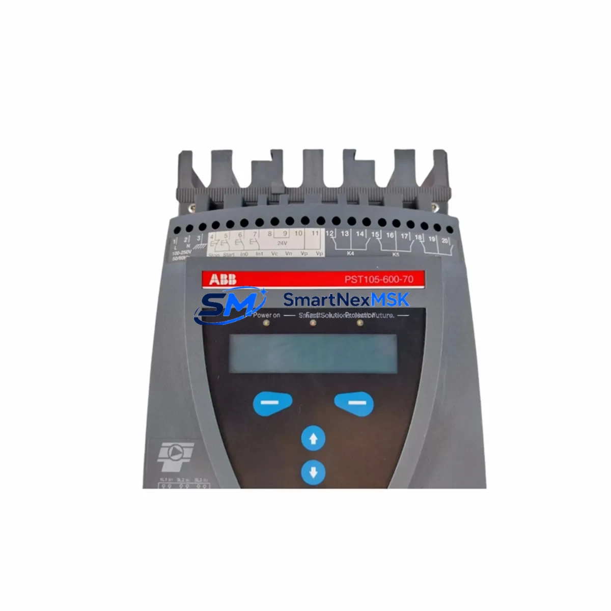
ABB PST105-600-70 Retrofit-Ready Soft Starter for PST Series Control Systems
The ABB PST105-600-70 is a 105 A / 600 V / 70 kW three-phase soft starter engineered for seamless retrofit integration into existing PST Series motor control systems. Whether you are replacing an end-of-life ABB PST72-600-70, decommissioning a legacy PSTB105-600-70 bypass unit, or upgrading a control cabinet that has been running on discontinued firmware, the PST105-600-70 delivers a mechanically and electrically compatible drop-in solution that minimises engineering rework and keeps your production line moving.
Industrial facilities operating ABB drives and starters from the PST, PSTB, and PSR families frequently encounter obsolescence challenges: original spare parts become unavailable, lead times stretch to months, and the cost of unplanned downtime far exceeds the cost of a proactive upgrade. The PST105-600-70 addresses this directly. Its terminal layout mirrors the legacy PST Series footprint, allowing existing 6-wire control wiring — including the run, top-of-ramp, and bypass relay outputs — to be reconnected without re-routing cable trays or modifying DIN-rail spacing inside the control cabinet.
Before committing to a retrofit, engineers should verify four critical parameters: (1) supply voltage compatibility — the PST105-600-70 accepts 208–600 V AC, 50/60 Hz; (2) control supply voltage, which must match the existing 110 V AC or 24 V DC auxiliary circuit; (3) motor full-load current, which must not exceed 105 A continuous; and (4) the bypass contactor rating if the original installation used an external bypass such as the ABB AF116 or AF145 contactor series. Where the original panel used an integrated bypass block (PSTB variant), the PST105-600-70 can be paired with a new external bypass contactor without structural modification to the enclosure.
Upgrade Compatibility Table
| Parameter | Legacy PST72-600-70 / PSTB105 | PST105-600-70 (This Unit) | Retrofit Note |
|---|---|---|---|
| Rated Current | 72 A / 105 A (bypass) | 105 A continuous | Verify motor FLA ≤ 105 A before swap |
| Supply Voltage | 208–600 V AC | 208–600 V AC | Direct compatible — no transformer change |
| Control Voltage | 110 V AC or 24 V DC | 110 V AC or 24 V DC | Match existing auxiliary circuit |
| Terminal Layout | 1L1/3L2/5L3 → 2T1/4T2/6T3 | 1L1/3L2/5L3 → 2T1/4T2/6T3 | Direct re-termination; no re-routing required |
| Communication | Modbus RTU (optional card) | Modbus RTU (optional card) | Retain existing fieldbus card if installed |
| Mounting | DIN rail / panel mount | DIN rail / panel mount | Same footprint — no enclosure modification |
| Bypass Contactor | Integrated (PSTB) or external | External (AF116 / AF145 recommended) | Add external bypass if replacing PSTB variant |
| Commissioning Tool | Local keypad / DIP switches | Local keypad / DIP switches | No software licence required for basic setup |
| Warranty | Original OEM (expired) | 12-Month Warranty | Covered from date of shipment |
Retrofit Planning for Existing Automation Systems
A successful PST105-600-70 retrofit begins well before the maintenance window opens. Start by pulling the existing panel drawings and confirming the control circuit architecture. Many PST Series installations share a common control bus with other ABB components — including the ACS550 or ACS310 variable-frequency drives handling ancillary conveyors, the CP600 or CP400 HMI panels displaying motor status, and the AC500 or S500 PLC rack managing the sequencing logic. Understanding how the soft starter’s top-of-ramp relay feeds the PLC digital input — typically wired to an S500 DI module such as the DC532 — is essential before any power is removed.
Terminal block identification is the next step. In older installations, the control wiring may terminate on Phoenix Contact or Weidmüller terminal strips that are labelled according to a legacy numbering scheme. Cross-reference these against the PST105-600-70 wiring diagram (document 1SFC132081M0201) to confirm that the enable input, fault relay, and thermistor input terminals align. Where a Modbus RTU communication card (MFCARD-COM-MODBUS) was fitted to the original unit, the same card can be transferred to the PST105-600-70 — preserving the existing register map and avoiding any changes to the SCADA or DCS configuration running on the upstream control system.
For facilities using an ABB System 800xA or Freelance DCS, the soft starter typically appears as a device object within the control network. Provided the Modbus node address and baud rate settings are replicated on the replacement unit using the front-panel keypad, the DCS will recognise the new device without requiring a database rebuild. Similarly, if the motor protection relay — such as an ABB M102-M or a legacy SPAM150C — is wired in series with the starter’s fault output, its trip settings should be documented and verified post-installation to ensure coordination is maintained.
I/O expansion considerations are equally important in multi-motor panels. Where the PST105-600-70 shares a control cabinet with additional starters or with an ABB UMC100 universal motor controller, confirm that the 24 V DC auxiliary supply rail has sufficient capacity to power the new unit’s control electronics alongside existing loads. A typical PST105-600-70 draws approximately 10 VA from the control supply — a figure that should be added to the panel’s power budget before the retrofit is approved.
Downtime Control During System Migration
Minimising production downtime during a soft starter replacement requires a structured approach. Begin by scheduling the swap during a planned maintenance window and preparing a pre-tested replacement unit — ideally one that has been bench-tested against a resistive load to confirm correct ramp-up behaviour and fault relay operation before it reaches the plant floor.
Preserve the original PLC program by uploading a backup from the AC500 or S500 controller before any wiring is disturbed. If the HMI — whether a CP600 panel or a third-party SCADA screen — displays motor current or starter status, note the current tag addresses so they can be verified against live values after the replacement is energised. This step takes less than five minutes but eliminates the most common source of post-retrofit commissioning delays.
During the physical swap, label every control wire before disconnection using the panel drawing reference. Re-terminate in the same sequence, torque all power terminals to the specified 4 Nm, and perform an insulation resistance test on the motor circuit before closing the main isolator. Set the PST105-600-70’s current rating dial to match the motor nameplate FLA, configure the ramp time to match the original setting (typically 5–15 seconds for conveyor and pump applications), and enable the top-of-ramp output if a bypass contactor is used.
After energisation, monitor the first three start cycles from the HMI or from the starter’s front display. Confirm that the current during ramp does not exceed 3× FLA, that the top-of-ramp relay closes within the expected window, and that no fault codes are logged. With these steps completed, the system can be returned to automatic control — typically within a two-hour maintenance window for a prepared team.
Retrofit Support FAQ
Q1: Is the PST105-600-70 a direct replacement for the PST72-600-70?
The PST105-600-70 is electrically and mechanically compatible with the PST72-600-70 installation footprint. The key difference is the higher continuous current rating (105 A vs. 72 A), which makes it suitable as an uprated replacement where motor load has increased or where a margin of safety is required. No enclosure modification is needed.
Q2: Can I reuse the existing control wiring and Modbus card?
Yes. The terminal layout and optional Modbus RTU communication card (MFCARD-COM-MODBUS) are compatible with the PST105-600-70. Transfer the card from the original unit, replicate the node address and baud rate settings via the front keypad, and the upstream PLC or DCS will communicate with the replacement unit without register-map changes.
Q3: What commissioning checks are performed before shipment?
Each PST105-600-70 unit supplied by SMARTNEXMSK undergoes a pre-shipment functional test covering power-on self-test, control supply verification, relay output continuity, and parameter default confirmation. A test report is available on request. All units are covered by a 12-month warranty from the date of shipment.
Q4: What if my original installation used a PSTB bypass variant?
The PST105-600-70 does not include an integrated bypass. If your original panel used a PSTB105-600-70 with built-in bypass, you will need to add an external bypass contactor — the ABB AF116 or AF145 is the recommended pairing. SMARTNEXMSK can advise on contactor selection and supply the bypass contactor alongside the soft starter to simplify procurement.
© 2026 SMARTNEXMSK. All rights reserved.
Original Source: https://smartnexmsk.com
Contact: sales@smartnexmsk.com | +86 18259474341


